

Question: The figures below show a simplified model for a landing gear of a horizontal takeoff launch vehicle (A) consisting of a wheel (B) of
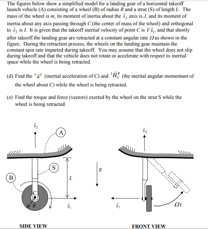
The figures below show a simplified model for a landing gear of a horizontal takeoff launch vehicle (A) consisting of a wheel (B) of radius R and a strut (S) of length L. The mass of the wheel is m, its moment of inertia about the 3 axis is J, and its moment of inertia about any axis passing through C (the center of mass of the wheel) and orthogonal to 3 is I. It is given that the takeoff inertial velocity of point C is Vs, and that shortly after takeoff the landing gear are retracted at a constant angular rate 2 as shown in the figure. During the retraction process, the wheels on the landing gear maintain the constant spin rate imparted during takeoff. You may assume that the wheel does not slip during takeoff and that the vehicle does not rotate or accelerate with respect to inertial space while the wheel is being retracted. (d) Find the 'a (inertial acceleration of C) and 'H (the inertial angular momentum of the wheel about C) while the wheel is being retracted. (e) Find the torque and force (vectors) exerted by the wheel on the strut S while the wheel is being retracted. $2 A B S L g R SIDE VIEW 15 $3 $2 FRONT VIEW
Step by Step Solution
There are 3 Steps involved in it

Get step-by-step solutions from verified subject matter experts