

Question: The following specifications are given for a SHAPING MACHINE: Number of strockes for the machine > Range of strocke Motor's HP Motor's speed
 Range">
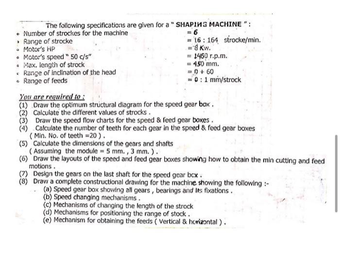
The following specifications are given for a "SHAPING MACHINE": Number of strockes for the machine > Range of strocke Motor's HP Motor's speed " 50 c/s" Max. length of strock Range of inclination of the head Range of feeds = 6 16 164 strocke/min. =8 Kw. = 1460 r.p.m. = 450 mm. =()+60 0:1 mm/strock You are required to: (1) Draw the optimum structural diagram for the speed gear box'. (2) Calculate the different values of strocks. (3) Draw the speed flow charts for the speed & feed gear boxes. (4) Calculate the number of teeth for each gear in the speed & feed gear boxes (Min. No. of teeth = 20). (5) Calculate the dimensions of the gears and shafts (Assuming the module = 5 mm., 3 mm.). (6) Draw the layouts of the speed and feed gear boxes showing how to obtain the min cutting and feed motions. (7) Design the gears on the last shaft for the speed gear bcx. (8) Draw a complete constructional drawing for the machine showing the following :- (a) Speed gear box showing all gears, bearings and Its fixations. (b) Speed changing mechanisms. (c) Mechanisms of changing the length of the strock (d) Mechanisms for positioning the range of stock. (e) Mechanism for obtaining the feeds (Vertical & horizontal). The following specifications are given for a "SHAPING MACHINE": Number of strockes for the machine > Range of strocke Motor's HP Motor's speed " 50 c/s" Max. length of strock Range of inclination of the head Range of feeds = 6 16 164 strocke/min. =8 Kw. = 1460 r.p.m. = 450 mm. =()+60 0:1 mm/strock You are required to: (1) Draw the optimum structural diagram for the speed gear box'. (2) Calculate the different values of strocks. (3) Draw the speed flow charts for the speed & feed gear boxes. (4) Calculate the number of teeth for each gear in the speed & feed gear boxes (Min. No. of teeth = 20). (5) Calculate the dimensions of the gears and shafts (Assuming the module = 5 mm., 3 mm.). (6) Draw the layouts of the speed and feed gear boxes showing how to obtain the min cutting and feed motions. (7) Design the gears on the last shaft for the speed gear bcx. (8) Draw a complete constructional drawing for the machine showing the following :- (a) Speed gear box showing all gears, bearings and Its fixations. (b) Speed changing mechanisms. (c) Mechanisms of changing the length of the strock (d) Mechanisms for positioning the range of stock. (e) Mechanism for obtaining the feeds (Vertical & horizontal). The following specifications are given for a "SHAPING MACHINE": Number of strockes for the machine > Range of strocke Motor's HP Motor's speed " 50 c/s" Max. length of strock Range of inclination of the head Range of feeds = 6 16 164 strocke/min. =8 Kw. = 1460 r.p.m. = 450 mm. =()+60 0:1 mm/strock You are required to: (1) Draw the optimum structural diagram for the speed gear box'. (2) Calculate the different values of strocks. (3) Draw the speed flow charts for the speed & feed gear boxes. (4) Calculate the number of teeth for each gear in the speed & feed gear boxes (Min. No. of teeth = 20). (5) Calculate the dimensions of the gears and shafts (Assuming the module = 5 mm., 3 mm.). (6) Draw the layouts of the speed and feed gear boxes showing how to obtain the min cutting and feed motions. (7) Design the gears on the last shaft for the speed gear bcx. (8) Draw a complete constructional drawing for the machine showing the following :- (a) Speed gear box showing all gears, bearings and Its fixations. (b) Speed changing mechanisms. (c) Mechanisms of changing the length of the strock (d) Mechanisms for positioning the range of stock. (e) Mechanism for obtaining the feeds (Vertical & horizontal). The following specifications are given for a "SHAPING MACHINE": Number of strockes for the machine > Range of strocke Motor's HP Motor's speed " 50 c/s" Max. length of strock Range of inclination of the head Range of feeds = 6 16 164 strocke/min. =8 Kw. = 1460 r.p.m. = 450 mm. =()+60 0:1 mm/strock You are required to: (1) Draw the optimum structural diagram for the speed gear box'. (2) Calculate the different values of strocks. (3) Draw the speed flow charts for the speed & feed gear boxes. (4) Calculate the number of teeth for each gear in the speed & feed gear boxes (Min. No. of teeth = 20). (5) Calculate the dimensions of the gears and shafts (Assuming the module = 5 mm., 3 mm.). (6) Draw the layouts of the speed and feed gear boxes showing how to obtain the min cutting and feed motions. (7) Design the gears on the last shaft for the speed gear bcx. (8) Draw a complete constructional drawing for the machine showing the following :- (a) Speed gear box showing all gears, bearings and Its fixations. (b) Speed changing mechanisms. (c) Mechanisms of changing the length of the strock (d) Mechanisms for positioning the range of stock. (e) Mechanism for obtaining the feeds (Vertical & horizontal).
Step by Step Solution
3.51 Rating (154 Votes )
There are 3 Steps involved in it

Get step-by-step solutions from verified subject matter experts