

Question: The following table represents the microcode for the simple CPU shown above. Each column represents the possible setting of the switches shown as small circles
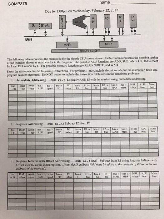
The following table represents the microcode for the simple CPU shown above. Each column represents the possible setting of the switches shown as small circles in the diagram The possible ALU functions are ADD, SUB, AND, OR, Increment by 1 and Decrement by 1. The possible memory functions are READ. WRITE, and WAIT. Show the microcode for the following instructions. For problem 1 only, include the microcode for the instruction fetch and program counter increment. Do NOT bother to include the instruction fetch steps in the remaining problems. Immediate Addressing- AND r1, 7 logically AND R1 with the number using immediate addressing. Register Addressing sub R1, R2 Subtract R2 from R1 Register Indirect with Offset Addressing nub R1, 3 [R2] Subtract front R1 using Register Indirect with Offset with R2 as the index register
Step by Step Solution
There are 3 Steps involved in it

Get step-by-step solutions from verified subject matter experts