

Question: The frame structure shown in Figure 1 is the support structure for a hoist located at the point of application of load W . The
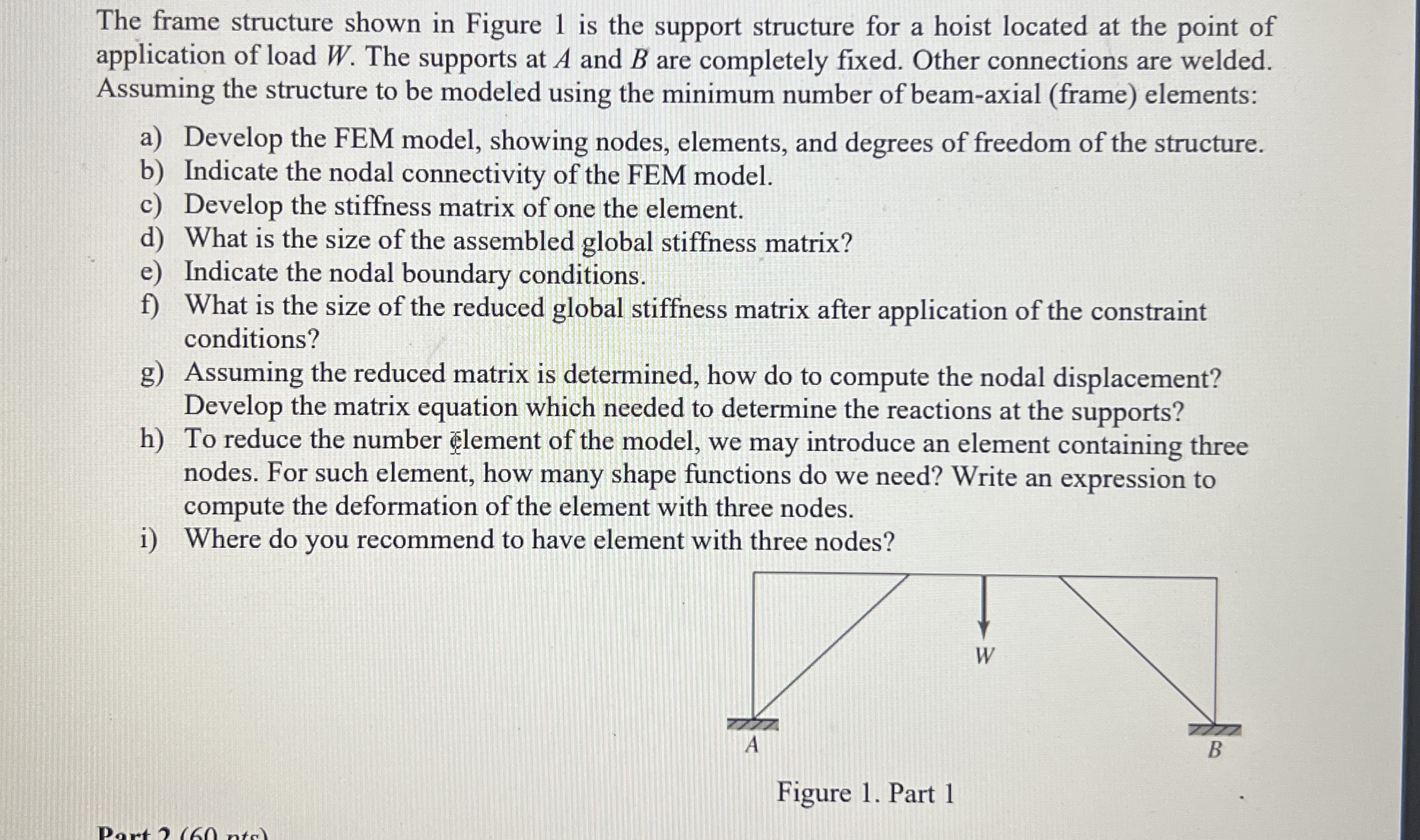
The frame structure shown in Figure is the support structure for a hoist located at the point of
application of load The supports at A and are completely fixed. Other connections are welded.
Assuming the structure to be modeled using the minimum number of beamaxial frame elements:
a Develop the FEM model, showing nodes, elements, and degrees of freedom of the structure.
b Indicate the nodal connectivity of the FEM model.
c Develop the stiffness matrix of one the element.
d What is the size of the assembled global stiffness matrix?
e Indicate the nodal boundary conditions.
f What is the size of the reduced global stiffness matrix after application of the constraint
conditions?
g Assuming the reduced matrix is determined, how do to compute the nodal displacement?
Develop the matrix equation which needed to determine the reactions at the supports?
h To reduce the number element of the model, we may introduce an element containing three
nodes. For such element, how many shape functions do we need? Write an expression to
compute the deformation of the element with three nodes.
i Where do you recommend to have element with three nodes?
Step by Step Solution
There are 3 Steps involved in it
1 Expert Approved Answer
Step: 1 Unlock

Question Has Been Solved by an Expert!
Get step-by-step solutions from verified subject matter experts
Step: 2 Unlock
Step: 3 Unlock