

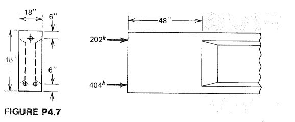
Question: The I - beam shown in Fig. P 4 . 7 is to be post - tensioned using three tendons, each containing seven 0 .
The Ibeam shown in Fig. P is to be posttensioned using three tendons, each containing seven in diameter Grade strands. They will be tensioned to an initial value P of kips each. To provide for anchorage hardware and to distribute concentrated forces, a solid end block will be provided having length equal to the member depth. Design the reinforcement for bursting and spalling tension for this beam, using closed hoop stirrups at an allowable stress f ksi. Note that the tendons will be tensioned in a sequence that can be specified by the designer. What is the minimum size bearing plate that can be used at the anchorages, given that the conduit carrying the tendons has outside diameter in and that no bearing is provided under this part of the plates. Concrete strengths are f ksi and f ksi. Describe any other reinforcement that would be provided in the end zone.FIGURE P
Step by Step Solution
There are 3 Steps involved in it
1 Expert Approved Answer
Step: 1 Unlock

Question Has Been Solved by an Expert!
Get step-by-step solutions from verified subject matter experts
Step: 2 Unlock
Step: 3 Unlock