

Question: The image shows a problem related to instruction execution in a basic processor architecture. Here's a breakdown: Instructions Format: The instructions are 1 0 -
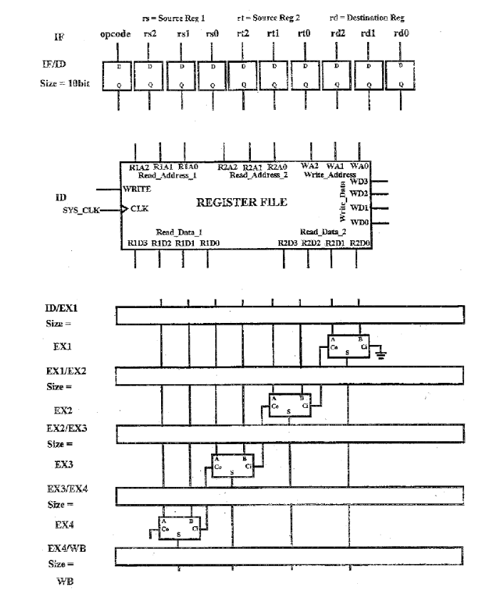
The image shows a problem related to instruction execution in a basic processor architecture. Here's a breakdown:
Instructions Format:
The instructions are bits long.
The opcode is a single bit:
for ADD addition operation
for NOP No operation
The ADD instruction format consists of:
bit for the opcode.
bits for the source register rs
bits for the source register rt
bits for the destination register rd
For ADD, the operation is: rd rs rt ie the destination register gets the sum of two source registers
The NOP instruction consists of all dontcare values indicated by x after the opcode.
Task:
Instructions are coming into the Instruction FetchInstruction Decode IFID register on every clock cycle, but instruction fetching is not your responsibility.
The task is to complete the datapath and control for the ADD and NOP instructions.
You need to mark the size of all the stage registers.
Control bits can be carried with the data in stage registers.
The final carry bit C is ignored, and only the bit result is stored.
Required Work:
You must complete the datapath for these operations, ensuring that the control signals, register sizes, and data flow are clearly marked. Additionally, the NOP instruction should have minimal impact on the pipeline.
Step by Step Solution
There are 3 Steps involved in it
1 Expert Approved Answer
Step: 1 Unlock

Question Has Been Solved by an Expert!
Get step-by-step solutions from verified subject matter experts
Step: 2 Unlock
Step: 3 Unlock