

Question: The ISP links: Fig. 1 . Basic network topology The ISP has allocated one of the following public IPv 4 address spaces for your group.
The ISP links: Fig. Basic network topology
The ISP has allocated one of the following public IPv address spaces for your group. A
address space will be used for each of the two ISP links:
The Internal Network:
As part of the network redesign, the AIT has allocated one of the following private address
spaces for your group for addressing the internal
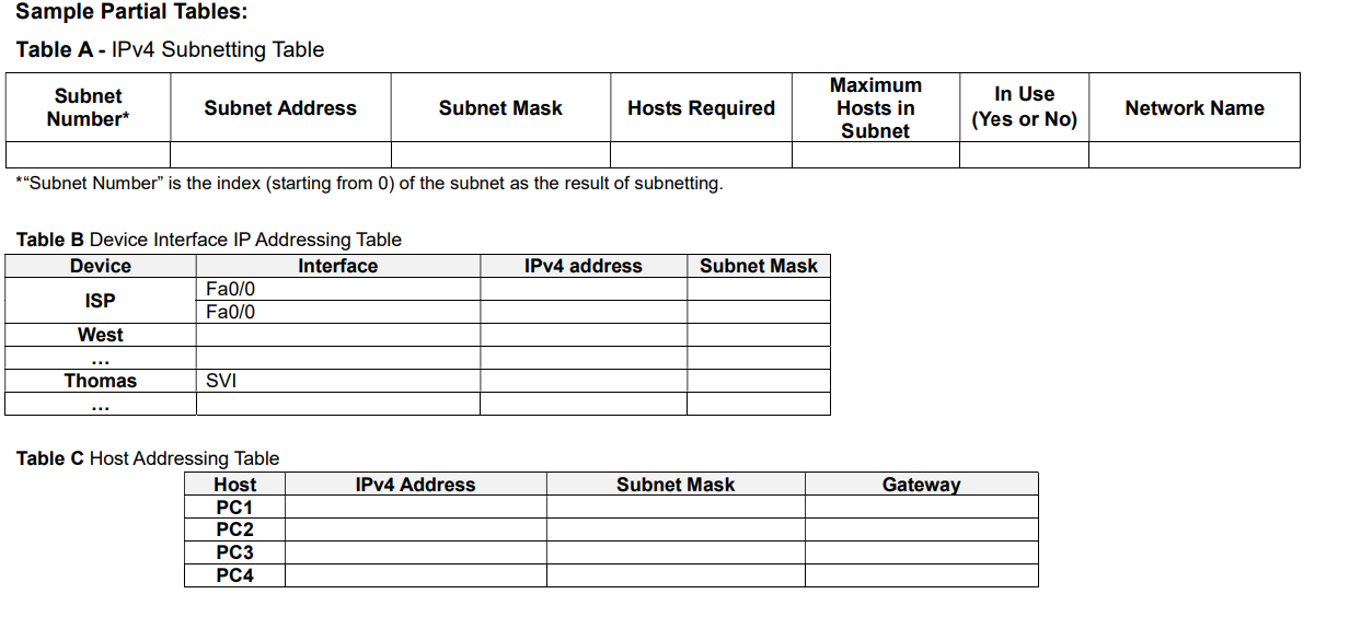
Sample Partial Tables:
Table A IPv Subnetting Table
Subnet Number" is the index starting from of the subnet as the result of subnetting.
Table B Device Interface IP Addressing Table
Table C Host Addressing Table
The expected numbers of users for each of the user groups are:
For the West switching network this will be implemented in VLANs:
hosts for Students
hosts for Staff
On the Main site:
hosts on the Server Farm LAN.
On the Branch site:
hosts in Students as shown in Appendix: Partial Topology Diagram
hosts in a spare LAN
The AIT requires that:
The use of VLSM design to maximise the use of IPv addresses.
All networking devices including switch SVIs must have IPv addresses and the PC hosts
gateways will use the first usable addresses in their subnet.
Each of the ISP links will be allocated a subnet mask of
The Management VLAN for the switching networks will have an extra host referred to as the
Network Admin Host as shown in the Topology Diagram for network administration usage.
At this stage, AIT agrees that it is sufficient to assign all hosts with an IPv address statically.
Milestone Submission: Tables A B and C
IPv Network subnetting Table A which shows possible subnets that meet the design
requirements; Subnets that are not used are to be clearly identified in each table not in use
Detailed IPv addressing tables Tables B and C showing all networking devices names and
their interface details. Note that, the gateways of the VLANs will be implemented as subinterfaces, eg Fa as the gateway of VLAN
Step by Step Solution
There are 3 Steps involved in it
1 Expert Approved Answer
Step: 1 Unlock

Question Has Been Solved by an Expert!
Get step-by-step solutions from verified subject matter experts
Step: 2 Unlock
Step: 3 Unlock