

Question: The post fault 2 2 kV network is shown in Figure Q 2 a . The network is only protected by overcurrent relay and the
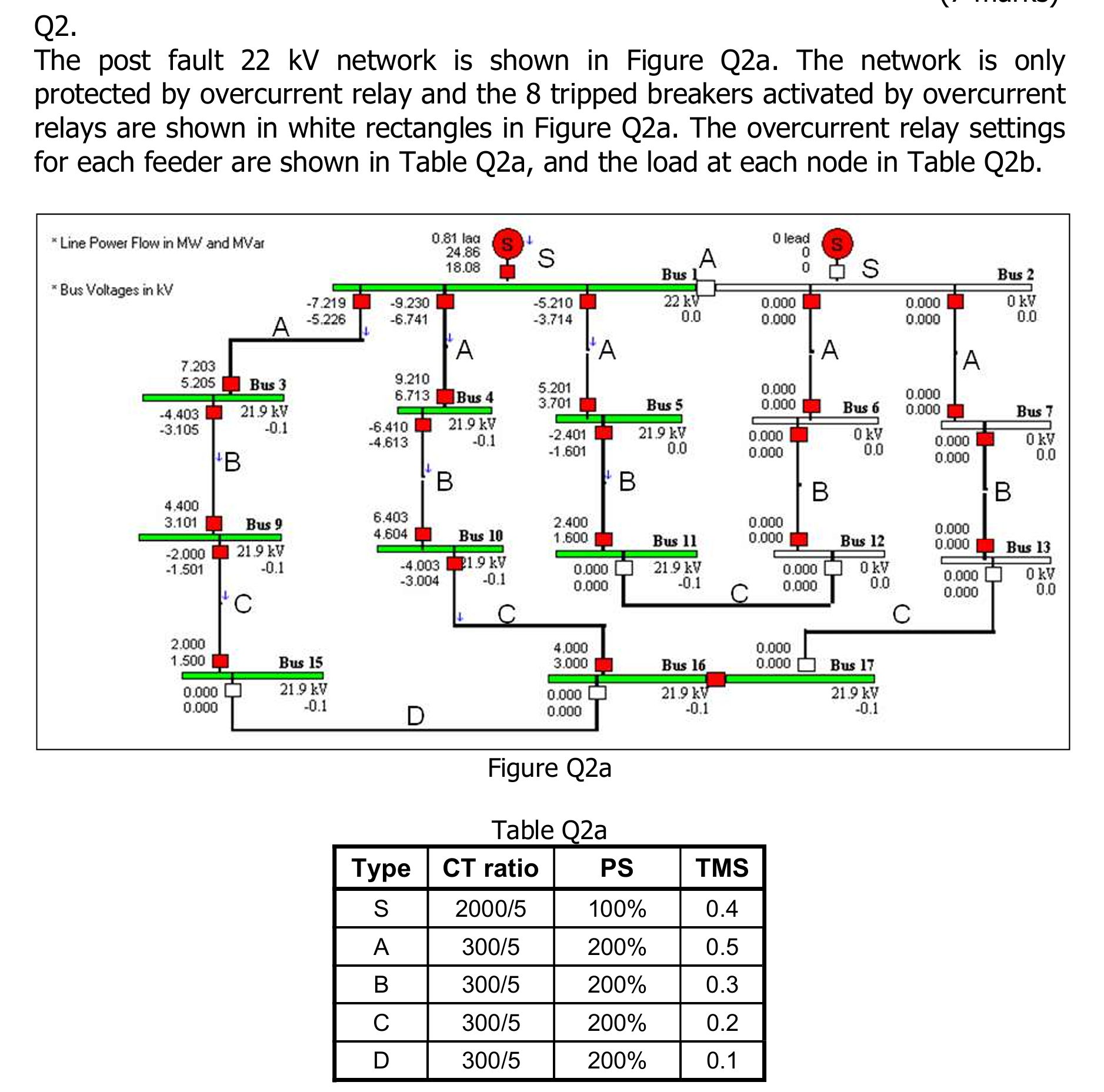
The post fault kV network is shown in Figure Qa The network is only protected by overcurrent relay and the tripped breakers activated by overcurrent relays are shown in white rectangles in Figure Qa The overcurrent relay settings for each feeder are shown in Table Qa and the load at each node in Table Qb
Figure Qa
Table Qa Table Qb
a Identify the possible fault location. Give reasons to support your fault diagnose inference.
marks
b The fault is subsequently cleared and supply has been all restored. However, on the next day, all breakers connected to Bus failed and cannot be closed as shown in Figure Qb As a result the feeder from Bus to Bus tripped resulting in a loss of supply to Bus Bus Bus Bus Bus Bus Bus Bus Bus and Bus List the appropriate switching steps so that supply to all nodes can be fully restored, or to as many nodes as possible. Determine the two highestloading circuits in amperes and also nodes that supply cannot be restored if any.
Step by Step Solution
There are 3 Steps involved in it
1 Expert Approved Answer
Step: 1 Unlock

Question Has Been Solved by an Expert!
Get step-by-step solutions from verified subject matter experts
Step: 2 Unlock
Step: 3 Unlock