

Question: The required steps, process, diagrams, and / or unknowns are specified below. The continuous beam with an internal hinge at node 2 is carrying loads
The required steps, process, diagrams, andor unknowns are specified below.
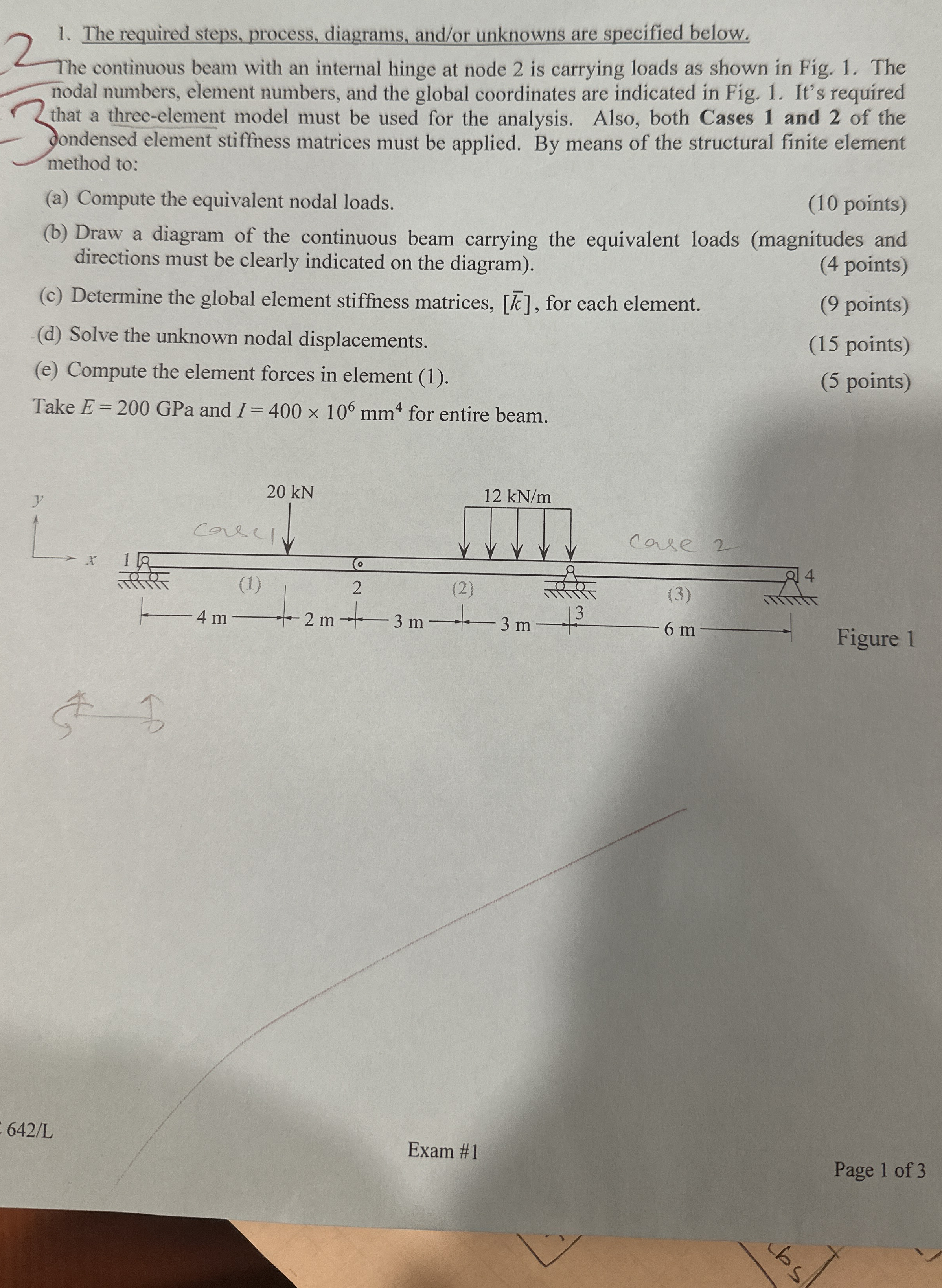
The continuous beam with an internal hinge at node is carrying loads as shown in Fig. The nodal numbers, element numbers, and the global coordinates are indicated in Fig. It's required that a threeelement model must be used for the analysis. Also, both Cases and of the ondensed element stiffness matrices must be applied. By means of the structural finite element method to:
a Compute the equivalent nodal loads.
points
b Draw a diagram of the continuous beam carrying the equivalent loads magnitudes and directions must be clearly indicated on the diagram
points
c Determine the global element stiffness matrices, for each element.
points
d Solve the unknown nodal displacements.
points
e Compute the element forces in element
points
Take GPa and for entire beam.
Exam #
Page of
Step by Step Solution
There are 3 Steps involved in it
1 Expert Approved Answer
Step: 1 Unlock

Question Has Been Solved by an Expert!
Get step-by-step solutions from verified subject matter experts
Step: 2 Unlock
Step: 3 Unlock