

Question: The RobotIn the first examples you are to determine the forward kinematics and a partial inverse kinematics for the following 5 degree - of -
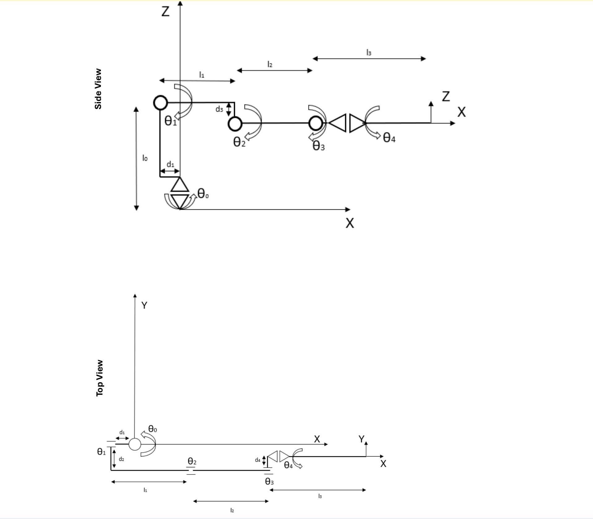
The RobotIn the first examples you are to determine the forward kinematics and a partial inverse kinematics for the following degreeoffreedom robot manipulator:see the figuresThe link length are defined as follows:lm lm lm lmIn addition there are multiple offsets that represent displacements at the joints.The offsets are dm between joint and joint d dbetween joint and joint and offset dm between joint and joint of this robot. The picture above shows the robot in the configuration where alljoint angles are The offset are defined as follows:dm dm dm dmThe simulator will actually show one additional joint joint correspondingto the opening of the gripper. This, however, is not relevant for the kinematicfunctions Determine and implement the forward kinematic function for this Robot.DerivationCode totalHere you are supposed to determine the transformation from configurationspace joint angles to the Cartesian location of the tool frame T inbase frame coordinates B using Homogeneous transformation. You onlyhave to provide the position. The orientation of the tool frame is not required.HINT: What effect does the last joint, have on the location of the toolframe For this part of the assignment you are to hand in a written version of theforward kinematics and your derivation either closed form or as a sequenceof transformation matrices and the code homogeneous or trigonometricfor the forward kinematic function you implemented.For the implementation you have to write the function fwd kin inside thefile kin fncsc This function has the following structure:fwdkintheta xdouble theta;double x;It gets passed in an array containing the joint angles theta the last anglecorresponds to the gripper and is of no interest here and should calculate x the dimensional position of the tool frame x x x y x z Determine a partial inverse kinematic function for the robot and implementit in the simulator. DerivationCode totalIn this part of the assignment you are to derive and implement an inversekinematic function for the robot manipulator for a specific orientation ofthe tool frame if multiple solutions exist only one is required here Thisorientation is given by and the requirement that the Xaxis of thetool frame is parallel to the Zaxis of the base frame but in the oppositedirection. In other words, the last link of the manipulator is to point straightdown. HINT: To determine this inverse kinematics you should decomposethe problem. You can determine and separately and calculate theother joint angles by analyzing the substructure formed by links and land l This requires moving the wrist frame to joint Again you are to hand in a written version of this inverse kinematics andits derivation and the code. The code here should be implemented in thefunction inv kininvkinx thetadouble x;double theta;This function gets passed in the location of the tool frame x and has tocompute a corresponding joint angle configuration thetaps:the code is not does not matters. I could not develop the math ways to its derivation.
I will upvote it thanks to ur efforts In advance.
And i will report the spam answers.
Step by Step Solution
There are 3 Steps involved in it
1 Expert Approved Answer
Step: 1 Unlock

Question Has Been Solved by an Expert!
Get step-by-step solutions from verified subject matter experts
Step: 2 Unlock
Step: 3 Unlock