

Question: the second pic is 4.24 Exercise 4.11 In this exercise we examine in detail how an instruction is executed in a single-cycle datapath. Problems in
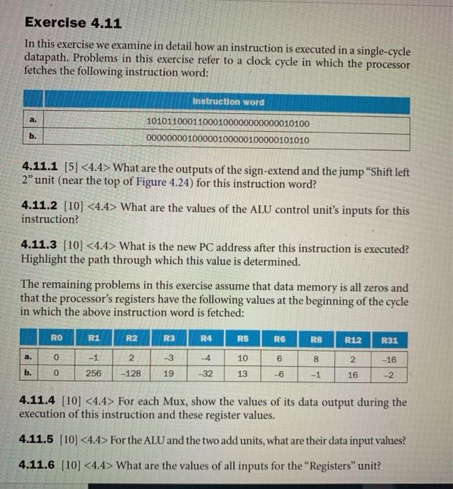
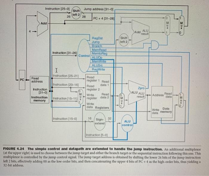
Exercise 4.11 In this exercise we examine in detail how an instruction is executed in a single-cycle datapath. Problems in this exercise refer to a clock cycle in which the processor fetches the following instruction word: Instruction word a. 10101100011000100000000000010100 00000000100000100000100000101010 b. 4.11.1 [5] What are the outputs of the sign-extend and the jump"Shift left 2" unit (near the top of Figure 4.24) for this instruction word? 4.11.2 [10] What are the values of the ALU control unit's inputs for this instruction? 4.11.3 [10] What is the new PC address after this instruction is executed? Highlight the path through which this value is determined. The remaining problems in this exercise assume that data memory is all zeros and that the processor's registers have the following values at the beginning of the cycle in which the above instruction word is fetched: RO R1 R2 R3 R4 R5 R6 R8 R12 R31 a. 0 -3 -4 10 6 8 2 -16 b. 0 256 128 19 -32 13 -6 -1 16 4.11.4 [10] For each Mux, show the values of its data output during the execution of this instruction and these register values. 4.11.5 [10] For the ALU and the two add units, what are their data input values? 4.11.6 (10] What are the values of all inputs for the "Registers" unit? Jump address (31-01 Instruction (25-01 Shift left 2 26 28 PC + 4 (31-28) Add XCE KES - Add ALU result 1 Shift left 2 RegDst Jump Branch MomRead Instruction (31-26] Momto Reg Control ALUOP I Memwaite ALUST 1 RegWrite Instruction (25-211 Read register 1 Road Instruction (20-161 Read data 1 register 2 Write Read Instruction (15-11] Write PC- Read address Zero ALU ALU Instruction (31-01 Instruction memory xCZ result Address Read data register data 2 emux) PXCE data Registers Witte Data data memory Instruction (15-01 16 32 Sign- extend ALU control Instruction 15-0) FIGURE 4.24 The simple control and datapath are extended to handle the Jump Instruction. An additional multiplexor (at the upper right) is used to choose between the jump target and either the branch target or the sequential instruction following this one. This multiplexor is controlled by the jump control signal. The jump target address is obtained by shifting the lower 26 bits of the jump instruction left 2 bits, effectively adding 00 as the low-order bits, and then concatenating the upper 4 bits of PC +4 as the high-order bits, thus yielding a 32-bit address
Step by Step Solution
There are 3 Steps involved in it

Get step-by-step solutions from verified subject matter experts