

Question: The simulation (linked below) is a side view of a set up for observing two-slit interference of light waves. A vertical barrier on the left
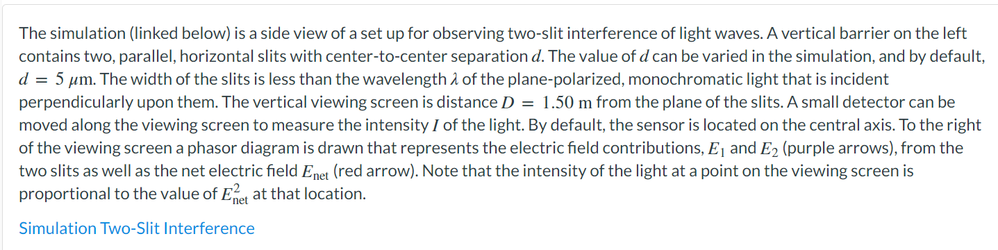
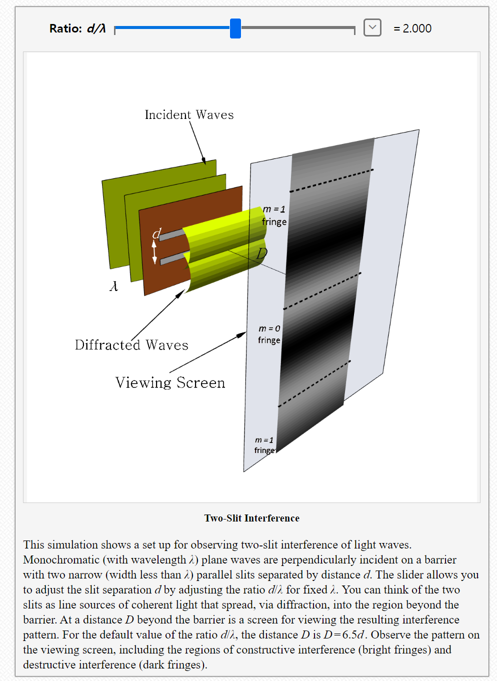
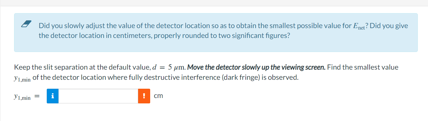
The simulation (linked below) is a side view of a set up for observing two-slit interference of light waves. A vertical barrier on the left contains two, parallel, horizontal slits with center-to-center separation d. The value of d can be varied in the simulation, and by default, d = 5 pm. The width of the slits is less than the wavelength A of the planepolarized, monochromatic light that is incident perpendicularly upon them. The vertical viewing screen is distance D = 1.50 m from the plane of the slits. A small detector can be moved along the viewing screen to measure the intensity I of the light. By default, the sensor is located on the central axis. To the right of the viewing screen a phasor diagram is drawn that represents the electric eld contributions, E] and E2 (purple arrows), from the two slits as well as the net electric eld Enet (red arrow). Note that the intensity of the light at a point on the viewing screen is proportional to the value of Bi, at that location. Simulation Two-Slit Interference Ratio: d/A lIl =2.ooo Incident Waves Diffracted Waves Viewing Screen TwoSlit Interference This simulation shows a set up for observing two-slit interference of light waves. Monochromatic (with wavelength A) plane waves are perpendicularly incident on a barrier with two narrow (width less than it) parallel slits separated by distance d. The slider allows you to adjust the slit separation d by adjusting the ratio d/A for fixed 3.. You can think of the two slits as line sources of coherent light that spread, via diffraction, into the region beyond the barrier. At a distance D beyond the barrier is a screen for viewing the resulting interference pattern. For the default value of the ratio all, the distance D is D: 6.507. Observe the pattern on the viewing screen, including the regions of constructive interference (bright fringes) and destructive interference (dark fringes). I Did you slowly adjust the value of the detector location so as to obtain the smallest possible value for Em? Did you give the detector location in centimeters, properly rounded to two signicant gures? Keep the slit separation at the default value, d = 5 pm. Move the detector slowly up the viewingscmen. Find the smallest value J'1,min of the detector location where fully destructive interference (dark fringe} is observed. m = :l cm
Step by Step Solution
There are 3 Steps involved in it

Get step-by-step solutions from verified subject matter experts