

Question: The single-phase full-wave rectifier of Figure below has L = 6.5 mH, R=2.5 92, and E= 10 V. The input voltage is V, =
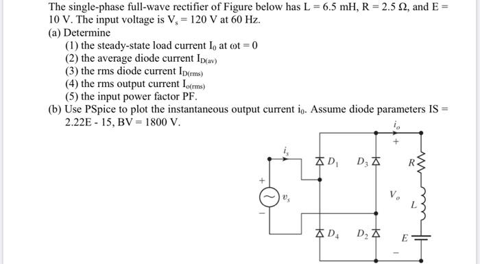
The single-phase full-wave rectifier of Figure below has L = 6.5 mH, R=2.5 92, and E= 10 V. The input voltage is V, = 120 V at 60 Hz. (a) Determine (1) the steady-state load current I, at cot = 0 (2) the average diode current Ip(av) (3) the rms diode current Ip(rms) (4) the rms output current lorms) (5) the input power factor PF. (b) Use PSpice to plot the instantaneous output current io. Assume diode parameters IS = 2.22E-15, BV = 1800 V. D D D3 A D G
Step by Step Solution
3.61 Rating (176 Votes )
There are 3 Steps involved in it
a 1 Determine the steadystate load current la at t0 The steadystate load current is the current that flows through the load when the rectifier has rea... View full answer

Get step-by-step solutions from verified subject matter experts