

Question: Repeat Problem 2.8 for the half-wave rectifier in Figure 2.2(a). Data From Problem 2.8:- The output resistance of the full-wave rectifier in Figure 2.6 (a)
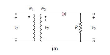
Repeat Problem 2.8 for the half-wave rectifier in Figure 2.2(a).
Data From Problem 2.8:-
The output resistance of the full-wave rectifier in Figure 2.6 (a) in the text is \(R=150 \Omega\). A filter capacitor is connected in parallel with \(R\). Assume \(V_{\gamma}=0.7 \mathrm{~V}\). The peak output voltage is to be \(12 \mathrm{~V}\) and the ripple voltage is to be no more than \(0.3 \mathrm{~V}\). The input frequency is \(60 \mathrm{~Hz}\).
(a) Determine the required rms value of \(v_{S}\).
(b) Determine the required filter capacitance value.
(c) Determine the peak current through each diode.
Figure 2.6:-
![N: N + D3 [us] D3 ww 13 (a) ww R +](https://dsd5zvtm8ll6.cloudfront.net/images/question_images/1714/8/1/0/6276635ef0347d9a1714810625630.jpg)
Figure 2.2(a):-
N: N + D3 [us] D3 ww 13 (a) ww R + Alone (c) 3T 2T (b) R Figure 2.6 A full-wave bridge rectifier: (a) circuit showing the current direction for a positive input cycle, (b) current direction for a negative input cycle, and (c) input and output voltage waveforms
Step by Step Solution
3.39 Rating (152 Votes )
There are 3 Steps involved in it
quad a vSmath... View full answer

Get step-by-step solutions from verified subject matter experts