

Question: The solid rod shown in the enclosed sketch is supported by frictionless gears at A and F, and it is loaded with the indicated
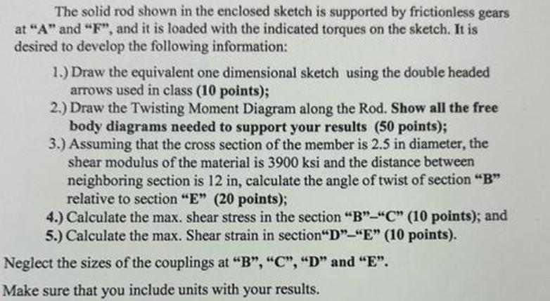
The solid rod shown in the enclosed sketch is supported by frictionless gears at "A" and "F", and it is loaded with the indicated torques on the sketch. It is desired to develop the following information: 1.) Draw the equivalent one dimensional sketch using the double headed arrows used in class (10 points); 2.) Draw the Twisting Moment Diagram along the Rod. Show all the free body diagrams needed to support your results (50 points); 3.) Assuming that the cross section of the member is 2.5 in diameter, the shear modulus of the material is 3900 ksi and the distance between neighboring section is 12 in, calculate the angle of twist of section "B" relative to section "E" (20 points); 4.) Calculate the max. shear stress in the section "B"-"C" (10 points); and 5.) Calculate the max. Shear strain in section"D"-"E" (10 points). Neglect the sizes of the couplings at "B", "C", "D" and "E". Make sure that you include units with your results.
Step by Step Solution
3.37 Rating (153 Votes )
There are 3 Steps involved in it
Solutions Step 1 The answer provided below has been developed in a clear s... View full answer

Get step-by-step solutions from verified subject matter experts