

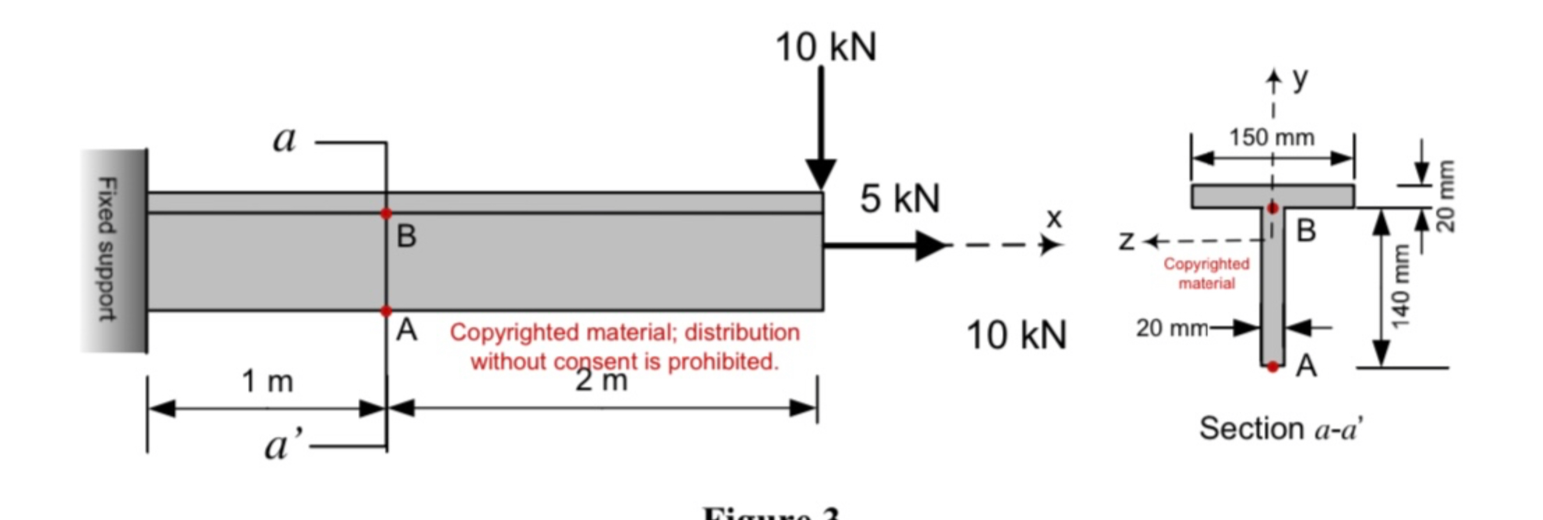
Question: The T - section cantilever beam shown in Fig. 3 is subjected to the loading shown in the figure. Axes y and z are the
The Tsection cantilever beam shown in Fig. is subjected to the loading shown in the figure. Axes
y and z are the centroidal axes of the section.
a Determine the internal forces N V M at section aa points
b With the internal forces found in part a determine the state of stress at point A bottom of web Draw your results on an element located at this point. points
c With the internal forces found in part a determine the state of stress at point B top of web Draw your results on an element located at this point. points
Step by Step Solution
There are 3 Steps involved in it
1 Expert Approved Answer
Step: 1 Unlock

Question Has Been Solved by an Expert!
Get step-by-step solutions from verified subject matter experts
Step: 2 Unlock
Step: 3 Unlock