

Question: The three circuits demonstrated below are implementing the same logic. Assuming the output load at the output of every circuits is 3 0 0 C
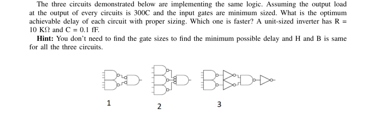
The three circuits demonstrated below are implementing the same logic. Assuming the output load at the output of every circuits is C and the input gates are minimum sized. What is the optimum achievable delay of each circuit with proper sizing. Which one is faster? A unitsized inverter has and
Hint: You don't need to find the gate sizes to find the minimum possible delay and H and B is same for all the three circuits.
Step by Step Solution
There are 3 Steps involved in it
1 Expert Approved Answer
Step: 1 Unlock

Question Has Been Solved by an Expert!
Get step-by-step solutions from verified subject matter experts
Step: 2 Unlock
Step: 3 Unlock