

Question: The U - beam ( AE ) shown in Figure Q 4 is simply supported and constructed by nailing three wooden planks. All loads are
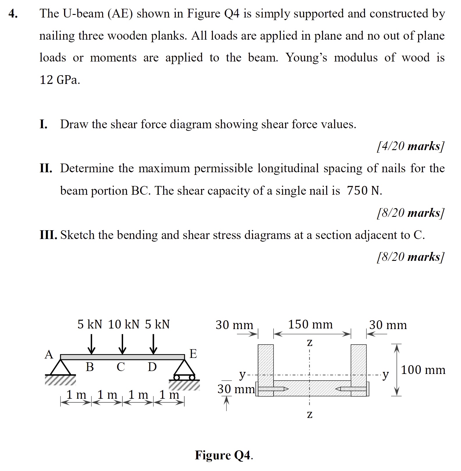
The Ubeam AE shown in Figure Q is simply supported and constructed by
nailing three wooden planks. All loads are applied in plane and no out of plane
loads or moments are applied to the beam. Young's modulus of wood is
GPa.
I. Draw the shear force diagram showing shear force values.
marks
II Determine the maximum permissible longitudinal spacing of nails for the
beam portion The shear capacity of a single nail is
marks
III. Sketch the bending and shear stress diagrams at a section adjacent to C
marks
Figure Q
Step by Step Solution
There are 3 Steps involved in it
1 Expert Approved Answer
Step: 1 Unlock

Question Has Been Solved by an Expert!
Get step-by-step solutions from verified subject matter experts
Step: 2 Unlock
Step: 3 Unlock