

Question: . Thinkabout 35.1 - Forces on a circle a+ Consider the Figure below for the following Thinkabout. You may want to refer to the Angular
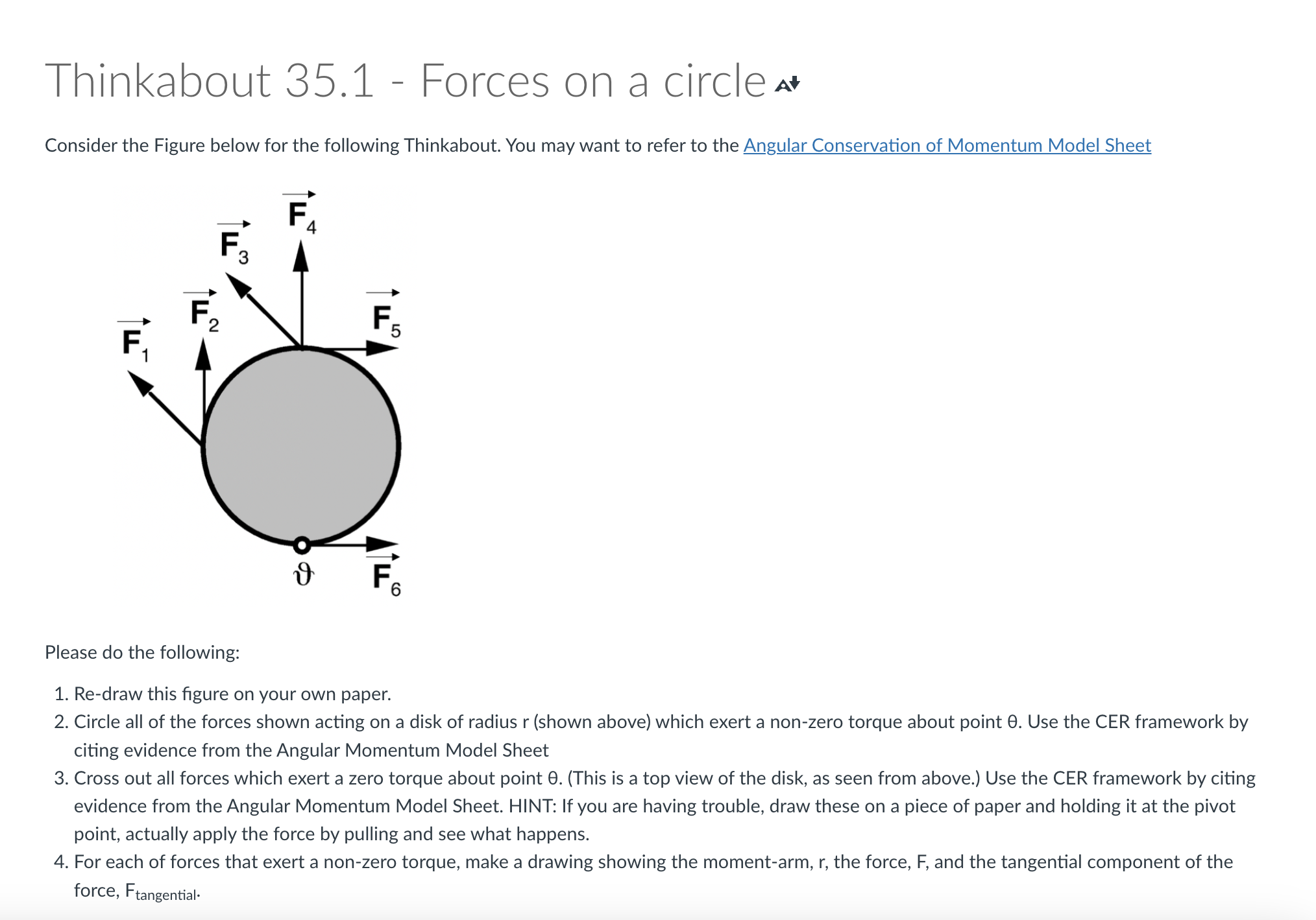
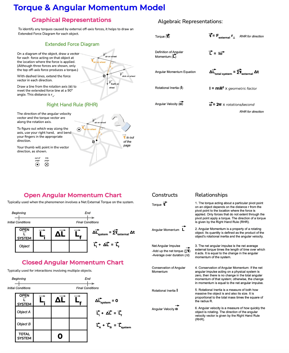
. Thinkabout 35.1 - Forces on a circle a+ Consider the Figure below for the following Thinkabout. You may want to refer to the Angular Conservation of Momentum Model Sheet Please do the following: 1. Re-draw this figure on your own paper. 2. Circle all of the forces shown acting on a disk of radius r (shown above) which exert a non-zero torque about point 8. Use the CER framework by citing evidence from the Angular Momentum Model Sheet 3. Cross out all forces which exert a zero torque about point 6. (This is a top view of the disk, as seen from above.) Use the CER framework by citing evidence from the Angular Momentum Model Sheet. HINT: If you are having trouble, draw these on a piece of paper and holding it at the pivot point, actually apply the force by pulling and see what happens. 4. For each of forces that exert a non-zero torque, make a drawing showing the moment-arm, r, the force, F, and the tangential component of the force, Frangential- Thinkabout 35.2 - Right hand rule a For each of the forces in Thinkabout 35.1 that exerts a non-zero torque about point 6, use the right-hand-rule to state whether the torque points out of the plane of the drawing or into the plane of the drawing. Use the CER framework (you can cite the Angular Momentum Conservation Model as evidence) Thinkabout 35.3 - Balancing Torques and Forces a Now we pin the disk (in Thinkabout 35.1) in place at the pivot point so that the disk can rotate freely about the pin. Suppose there are only 3 forces, 3, {,, and whatever force the pin exerts, on the disc (i.e. no force of gravity in this problem). Could both the torques and the forces be balanced in this problem? Explain. Include in your explanation drawings of the appropriate force diagram and extended force diagram. Here is the Angular Momentum Model to help with your thinking. Torque & Angular Momentum Model Graphical Representations Algebraic Representations: To identify any torques caused by external off-axis forces, it helps to draw an Extended Force Diagram for each object. Torque (t) = Fexternal 1 RHR for direction Extended Force Diagram On a diagram of the object, draw a vector- Definition of Angular L = 10* for each force acting on that object at Fair on wheel Momentum (L) the location where the force is applied Fair on wheel (Although three forces are shown, only the top off-axis force produces a torque.) F click on wheel Angular Momentum Equation ALtotal system = ET external At With dashed lines, extend the force vector in each direction. FEarth on Draw a line from the rotation axis (8) to wheel Rotational Inertia (I) meet the extended force line at a 90 I = mR2 X geometric factor angle. This distance is 1. Right Hand Rule (RHR) Angular Velocity () @ = 2TT X rotations/second The direction of the angular velocity RHR for direction vector and the torque vector are along the rotation axis Fair on wheel To figure out which way along the on wheel axis, use your right hand, and bend your fingers in the appropriate T is out direction. of the Your thumb will point in the vector page direction, as shown. out of Open Angular Momentum Chart Constructs Relationships Typically used when the phenomenon involves a Net External Torque on the system. Torque 1. The torque acting about a particular pivot point on an object depends on the distance r from the Beginning End pivot point to the location where the force is applied. Only forces that do not extent through the pivot point apply a torque. The direction of a torque Initial Conditions Final Conditions is given by the Right Hand Rule (RHR) OPEN Angular Momentum L 2. Angular Momentum is a property of a rotating AL LE AL system ETexternal At object. Its quantity is defined as the product of the SYSTEM object's rotational inertia and the angular velocity. Object 4 + At = , Net Angular Impulse 3. The net angular impulse is the net average Add up the net torque (ET) external torque times the length of time over which -Average over duration (At) it acts. It is equal to the change in the angular momentum of the system Closed Angular Momentum Chart Conservation of Angular 4. Conservation of Angular Momentum: If the net Typically used for interactions involving multiple objects. Momentum angular impulse acting on a physical system is zero, then there is no change in the total angula Beginning End momentum of that system; otherwise, the change in momentum is equal to the net angular impulse Initial Conditions Final Conditions Rotational Inertia I 5. Rotational Inertia is a measure of both how OPEN massive the object is and also its size. It is AL AL system = 0 proportional to the total mass times the square of the radius R. SYSTEM Angular Velocity @ 6. Angular velocity is a measure of how quickly the Object A [ + At = t, object is rotating. The direction of the angular velocity vector is given by the Right Hand Rule (RHR). Object B C + LB = system TOTAL SYSTEM 0
Step by Step Solution
There are 3 Steps involved in it

Get step-by-step solutions from verified subject matter experts