

Question: ***THIS IS 1 QUESTION WITH MULTIPLE SMALL PARTS WITHIN IT THAT COULDN'T BE FIT IN 1 PICTURE*** In this problem we assume that the logic
***THIS IS 1 QUESTION WITH MULTIPLE SMALL PARTS WITHIN IT THAT COULDN'T BE FIT IN 1 PICTURE***
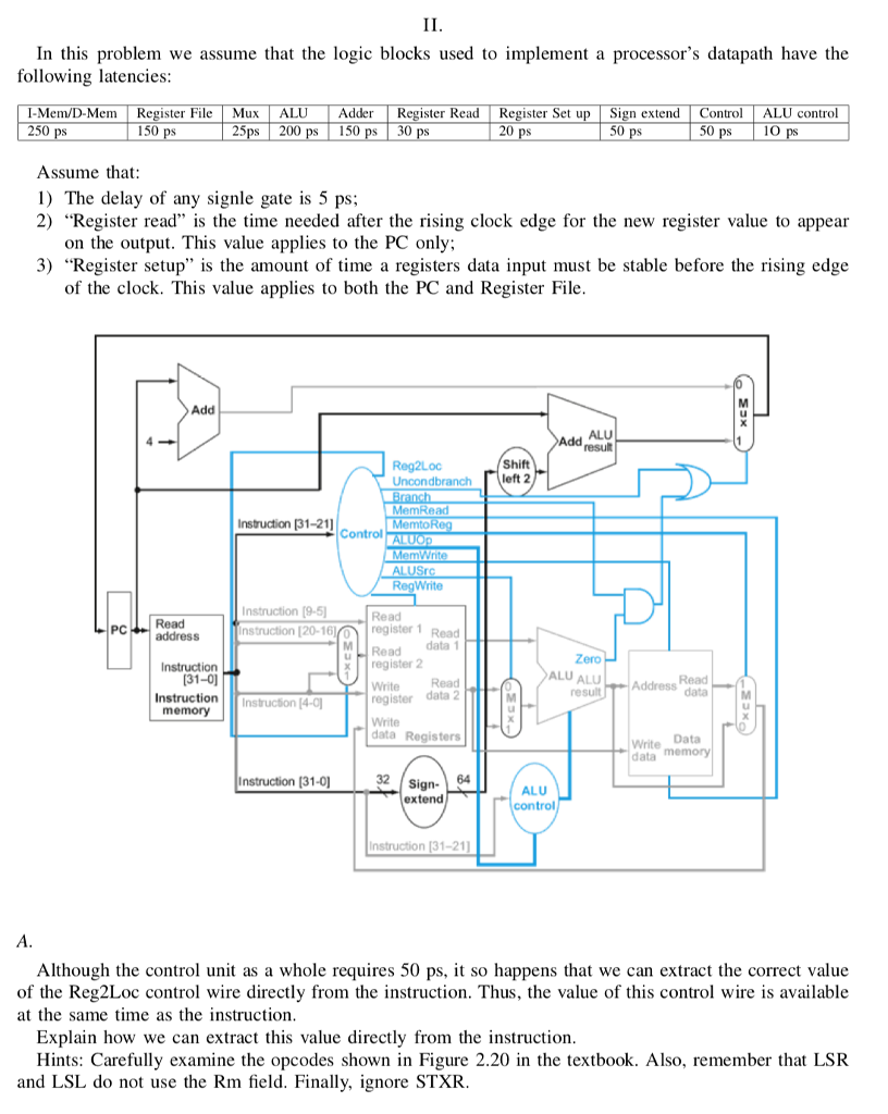
In this problem we assume that the logic blocks used to implement a processor's datapath have the following latencies: I-Mem/D-Mem Register FileMuxALUAdderRegister Read Register Set up Sign extendControALU control 250 150 25ps 200 p 150 30 20 50 1O Assume that 1) The delay of any signie gate is 5 ps; 2) "Register read" is the time needed after the rising clock edge for the new register value to appear on the output. This value applies to the PC only 3) "Register setup" is the amount of time a registers data input must be stable before the rising edge of the clock. This value applies to both the PC and Register File Add ALU Shift Uncondbrancheft 2 MemRead Instrudtion (31-211 Control RegWrite Instruction 19-5 nstruction [20-16 Read register PCRead address u Read data 1 ero Instruction register 2 (31-0 Read Write Read register data 2 result Instruction Instruction 14-0 memory data Registers Write Data data Instruction (31-0 32 Sign 64 ALU control extend Instruction [31-211 Although the control unit as a whole requires 50 ps, it so happens that we can extract the correct value of the Reg2Loc control wire directly from the instruction. Thus, the value of this control wire is available at the same time as the instruction Explain how we can extract this value directly from the instruction Hints: Carefully examine the opcodes shown in Figure 2.20 in the textbook. Also, remember that LSR and LSL do not use the Rm field. Finally, ignore STXR In this problem we assume that the logic blocks used to implement a processor's datapath have the following latencies: I-Mem/D-Mem Register FileMuxALUAdderRegister Read Register Set up Sign extendControALU control 250 150 25ps 200 p 150 30 20 50 1O Assume that 1) The delay of any signie gate is 5 ps; 2) "Register read" is the time needed after the rising clock edge for the new register value to appear on the output. This value applies to the PC only 3) "Register setup" is the amount of time a registers data input must be stable before the rising edge of the clock. This value applies to both the PC and Register File Add ALU Shift Uncondbrancheft 2 MemRead Instrudtion (31-211 Control RegWrite Instruction 19-5 nstruction [20-16 Read register PCRead address u Read data 1 ero Instruction register 2 (31-0 Read Write Read register data 2 result Instruction Instruction 14-0 memory data Registers Write Data data Instruction (31-0 32 Sign 64 ALU control extend Instruction [31-211 Although the control unit as a whole requires 50 ps, it so happens that we can extract the correct value of the Reg2Loc control wire directly from the instruction. Thus, the value of this control wire is available at the same time as the instruction Explain how we can extract this value directly from the instruction Hints: Carefully examine the opcodes shown in Figure 2.20 in the textbook. Also, remember that LSR and LSL do not use the Rm field. Finally, ignore STXR
Step by Step Solution
There are 3 Steps involved in it

Get step-by-step solutions from verified subject matter experts