

Question: /* This lab will demonstrate Pulse Width Modulation (PWM) by utilizing two pushbuttons and an LED on the launchpad. pushing button 1 (the one on
/* This lab will demonstrate Pulse Width Modulation (PWM) by utilizing two pushbuttons and an LED on the launchpad. pushing button 1 (the one on the left) will increase the dutycycle by a predetermined percentge defined in the array PWM[] and pushing buton 2 (the one on the right) will decrease the dutycycle.
The frequency of the analogWrite function is about 490 Hz
Change the LED define to blink other LEDs. */ #define LED RED_LED //#define LED GREEN_LED //#define LED YELLOW_LED
const int buttonPin1 = PUSH1; // the number of the pushbutton pin const int buttonPin2 = PUSH2; // the number of the pushbutton pin
int buttonState1 = 0; // variable for reading the pushbutton1 status int buttonState2 = 0; // variable for reading the pushbutton2 status unsigned int PWM = 0; // variable to hold PWM values
void setup() { // We don't have to use pinMode() when using analogWrite() but it doesn't // hurt to use it, especially if we want to call digitalWrite() for the // same pin in the same sketch. pinMode(LED, OUTPUT); // initialize the digital pin as an output. pinMode(buttonPin1,INPUT); //setting buttonPin1 to active LOW pinMode(buttonPin2, INPUT); //setting buttonPin2 to active LOW digitalWrite(LED, LOW); Serial.begin(9600); }
void loop() {
buttonState1 = digitalRead(buttonPin1); //check the state of the buttons buttonState2 = digitalRead(buttonPin2); while(digitalRead(buttonPin1)); //resolves the button debouncing issue. Program doesn't continue until button is released. while(digitalRead(buttonPin2)); if(buttonState1 == 1) //if button 1 is pressed --> send LED 100% duty cycle { PWM = 255; analogWrite(LED, PWM); //writes the analog value to LED pin Serial.println(PWM); delay(10); } if(buttonState2 == 1) //if button 2 is pressed --> send LED 0% duty cycle { PWM = 0; analogWrite(LED, PWM); Serial.println(PWM); delay(10); } }
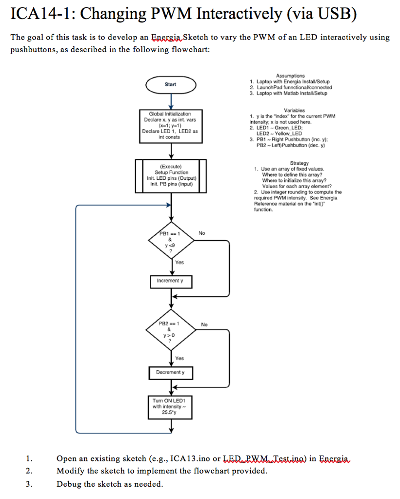
ICA14-1: Changing PWM Interactively (via USB) The goal of this task is to develop an EnergiaSketch to vary the PWM of an LED interactively using pushbuttons, as described in the following flowchart 1. Laptop with Energia Instal/Setup Start 3. Laptop with Matiab Install/Setup Variables Global Initialization Declare x, y as int. vars 1. y is the "index" for the current PWM intonsity, x is not used here. 2, LED Green LED; Declare LED 1, LED2 as int consts LED2-Yellow LED 3. PB1 Right Pushbutton (inc. y) PB2 Left)Pushbutton (dec. y) Strategy (Execute) Setup Function InitLED pins (Output) Init. PB pins (Input) 1. Use an array of foxed values. Where to define this array? Where to inisialize this array? Values for oach array olement? 2. Use integer rounding to compute the required PWM intensity. See Energia Reterence material on the "intO function No Yes Increment y No y>o Yes Decrement y Turn ON LED1 with intensity 25.5y Open an existing sketch (e.g., ICA13.ino or LED PWMJTestin) in Energia Modify the sketch to implement the flowchart provided Debug the sketch as needed ICA14-1: Changing PWM Interactively (via USB) The goal of this task is to develop an EnergiaSketch to vary the PWM of an LED interactively using pushbuttons, as described in the following flowchart 1. Laptop with Energia Instal/Setup Start 3. Laptop with Matiab Install/Setup Variables Global Initialization Declare x, y as int. vars 1. y is the "index" for the current PWM intonsity, x is not used here. 2, LED Green LED; Declare LED 1, LED2 as int consts LED2-Yellow LED 3. PB1 Right Pushbutton (inc. y) PB2 Left)Pushbutton (dec. y) Strategy (Execute) Setup Function InitLED pins (Output) Init. PB pins (Input) 1. Use an array of foxed values. Where to define this array? Where to inisialize this array? Values for oach array olement? 2. Use integer rounding to compute the required PWM intensity. See Energia Reterence material on the "intO function No Yes Increment y No y>o Yes Decrement y Turn ON LED1 with intensity 25.5y Open an existing sketch (e.g., ICA13.ino or LED PWMJTestin) in Energia Modify the sketch to implement the flowchart provided Debug the sketch as needed
Step by Step Solution
There are 3 Steps involved in it

Get step-by-step solutions from verified subject matter experts