

Question: This project involves the design and implementation of two interconnected digital circuits. The primary objective is to construct and analyze two specific circuit functionalities using
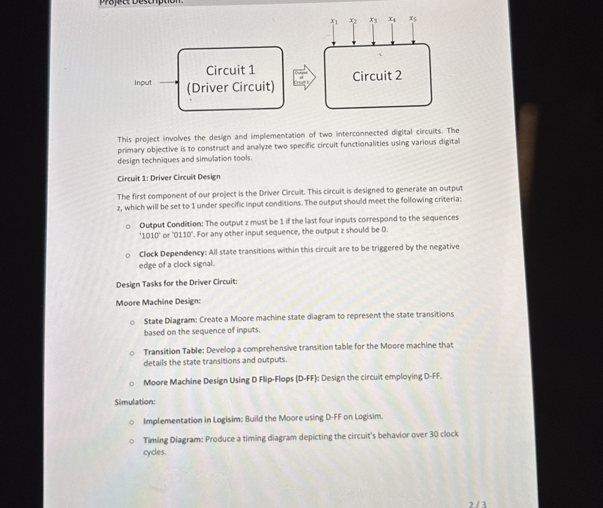
This project involves the design and implementation of two interconnected digital circuits. The primary objective is to construct and analyze two specific circuit functionalities using various digital design techniques and simulation tools.
Circuit : Driver Circuit Design
The first component of our project is the Driver Circuit. This circuit is designed to generate an output which will be set to under specific input conditions. The output should meet the following criteria:
Output Condition: The output must be if the last four inputs correspond to the sequences or For any other input sequence, the output should be
Clock Dependency: All state transitions within this circuit are to be triggered by the negative edge of a clock signal.
Design Tasks for the Driver Circuit:
Moore Machine Design:
State Diagram: Create a Moore machine state diagram to represent the state transitions based on the sequence of inputs.
Transition Table: Develop a comprehensive transition table for the Moore machine that details the state transitions and outputs.
Moore Machine Design Using D FlipFlops DFF: Design the circuit employing DFF
Simulation:
Implementation in Logisim: Build the Moore using DFF on Logisim.
Timing Diagram: Produce a timing diagram depicting the circuit's behavior over clock cycles.
Step by Step Solution
There are 3 Steps involved in it
1 Expert Approved Answer
Step: 1 Unlock

Question Has Been Solved by an Expert!
Get step-by-step solutions from verified subject matter experts
Step: 2 Unlock
Step: 3 Unlock