

Question: This project is to be done in Smalltalk programming language. This project is about building an Assembly Language Interpreter (ALI) for a Simple Assembly Lan-
This project is to be done in Smalltalk programming language.
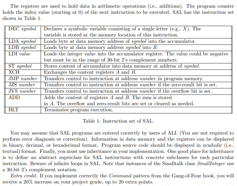
This project is about building an Assembly Language Interpreter (ALI) for a Simple Assembly Lan- guage (SAL). Fortunately for you SAL has a limited set of instructions, described below, which makes it easier to write the ALI. SAL programs are executed on a virtual (emulated) machine consisting of a memory, which stores program code and program data, an accumulator register, an additional register and a Program Counter (PC), which keeps track of the instruction being currently executed. Your ALI can execute SAL programs one line at a time (in a sort of debug mode) or at once until a halt instruc- tion is encountered. Also, your ALI will include a graphical user interface that displays various kinds of information: 1. An editor field that shows the state of computer memory in symbolic format (as opposed to binary or hex format 2. An action button for executing one line of code, starting from the first line of memory, numbered Line 0. See also the description of the Program Counter (PC) below 3. An action button for executing the entire program, starting from the current value of the PC 4. A set of widgets for displaying the content of the accumulator, additional register and PC. These widgets are updated each time one of the two action buttons above are selected. The computer hardware uses 30-bit words and consists of the following components 1. Memory. A 30-bit, word-addressable memory (RAM) for data, holding 256 words. Words are addressed by their location, starting from location 0 all the way up to location 255. Each location may either hold a signed integer in 2's complement notation or a SAL instruction 2. Accumulator. A 30-bit register. It is also known as Register A or A for short 3. Additional register. A 30-bit register also known as Register B or B for short 4. Program counter (PC). An 8-bit program counter (PC). The PC holds the address (number in program memory) of the next instruction to be executed. Before the program starts execution, the PC holds the value 0. It is subsequently updated as each instruction is executed. 5. A zero-result bit. This bit is set if the last ADD instruction produced a zero result. This bit is cleared if the last ADD instruction produced a result different from zero. The initial value is zero. The bit is changed only after ADD instructions are executed 6. An overflow bit. This bit is set whenever an ADD instruction produces an overflow (i.e., a result that cannot be stored in 2's complement notation with 30 bits). It is cleared if the ADD instruction did not produce an overflow. The initial value is zero. This project is about building an Assembly Language Interpreter (ALI) for a Simple Assembly Lan- guage (SAL). Fortunately for you SAL has a limited set of instructions, described below, which makes it easier to write the ALI. SAL programs are executed on a virtual (emulated) machine consisting of a memory, which stores program code and program data, an accumulator register, an additional register and a Program Counter (PC), which keeps track of the instruction being currently executed. Your ALI can execute SAL programs one line at a time (in a sort of debug mode) or at once until a halt instruc- tion is encountered. Also, your ALI will include a graphical user interface that displays various kinds of information: 1. An editor field that shows the state of computer memory in symbolic format (as opposed to binary or hex format 2. An action button for executing one line of code, starting from the first line of memory, numbered Line 0. See also the description of the Program Counter (PC) below 3. An action button for executing the entire program, starting from the current value of the PC 4. A set of widgets for displaying the content of the accumulator, additional register and PC. These widgets are updated each time one of the two action buttons above are selected. The computer hardware uses 30-bit words and consists of the following components 1. Memory. A 30-bit, word-addressable memory (RAM) for data, holding 256 words. Words are addressed by their location, starting from location 0 all the way up to location 255. Each location may either hold a signed integer in 2's complement notation or a SAL instruction 2. Accumulator. A 30-bit register. It is also known as Register A or A for short 3. Additional register. A 30-bit register also known as Register B or B for short 4. Program counter (PC). An 8-bit program counter (PC). The PC holds the address (number in program memory) of the next instruction to be executed. Before the program starts execution, the PC holds the value 0. It is subsequently updated as each instruction is executed. 5. A zero-result bit. This bit is set if the last ADD instruction produced a zero result. This bit is cleared if the last ADD instruction produced a result different from zero. The initial value is zero. The bit is changed only after ADD instructions are executed 6. An overflow bit. This bit is set whenever an ADD instruction produces an overflow (i.e., a result that cannot be stored in 2's complement notation with 30 bits). It is cleared if the ADD instruction did not produce an overflow. The initial value is zero
Step by Step Solution
There are 3 Steps involved in it

Get step-by-step solutions from verified subject matter experts