

Question: This question falls under Power Electronics. 1. a) Figure 1 shows the circuit arrangement for a six pulse fully controlled rectifier fed from a 3-phase
This question falls under Power Electronics.
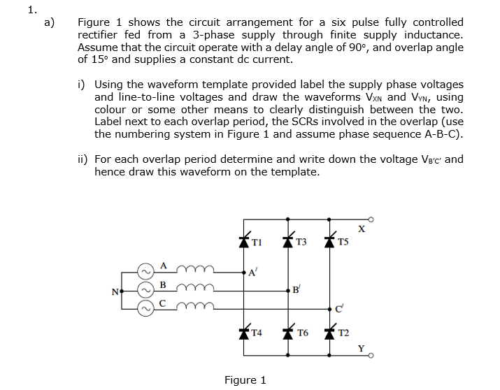
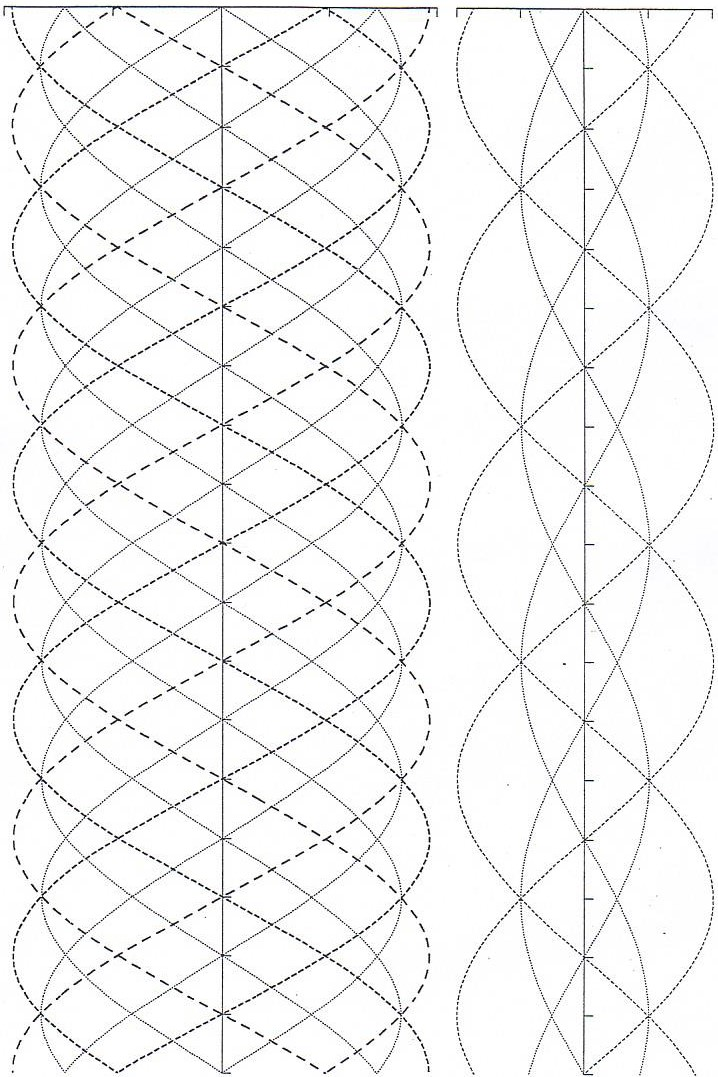
1. a) Figure 1 shows the circuit arrangement for a six pulse fully controlled rectifier fed from a 3-phase supply through finite supply inductance. Assume that the circuit operate with a delay angle of 90, and overlap angle of 15 and supplies a constant dc current. i) Using the waveform template provided label the supply phase voltages and line-to-line voltages and draw the waveforms VxN and Vyn, using colour or some other means to clearly distinguish between the two. Label next to each overlap period, the SCRs involved in the overlap (use the numbering system in Figure 1 and assume phase sequence A-B-C). ii) For each overlap period determine and write down the voltage Vec and hence draw this waveform on the template. x T3 TS A B N B c T4 T6 T2 Y Figure 1 1. a) Figure 1 shows the circuit arrangement for a six pulse fully controlled rectifier fed from a 3-phase supply through finite supply inductance. Assume that the circuit operate with a delay angle of 90, and overlap angle of 15 and supplies a constant dc current. i) Using the waveform template provided label the supply phase voltages and line-to-line voltages and draw the waveforms VxN and Vyn, using colour or some other means to clearly distinguish between the two. Label next to each overlap period, the SCRs involved in the overlap (use the numbering system in Figure 1 and assume phase sequence A-B-C). ii) For each overlap period determine and write down the voltage Vec and hence draw this waveform on the template. x T3 TS A B N B c T4 T6 T2 Y Figure 1
Step by Step Solution
There are 3 Steps involved in it

Get step-by-step solutions from verified subject matter experts