

a) Figure 1 shows the circuit arrangement for a six pulse fully controlled rectifier fed from a
Question:
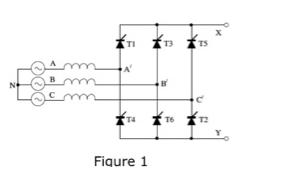
a) Figure 1 shows the circuit arrangement for a six pulse fully controlled rectifier fed from a 3- phase supply through finite supply inductance. Assume that the circuit operate with a delay angle of 90°, and overlap angle of 15° and supplies a constant dc current.
i) Using the waveform template provided label the supply phase voltages and line-to-line voltages and draw the waveforms VxN and Vyn, using colour or some other means to clearly distinguish between the two. Label next to each overlap period, the SCRs involved in the overlap (use the numbering system in Figure 1 and assume phase sequence A-B-C).
ii) For each overlap period determine and write down the voltage Vec and hence draw this waveform on the template.
b) Define the meaning of the terms displacement factor and distortion factor as applied to rectifier circuits. Give one example of a rectifier circuit that has a poor power factor dur to a poor distortion factor and one example that has a poor power factor due to a poor displacement factor. Sketch the arrangement of a 12-pulse diode bridge rectifier (assume series connection of bridge outputs) and explain why such circuits have a better power factor than their 6-pulse counterparts.
Expert Answer:


Fundamentals of Physics
ISBN: 978-0471758013
8th Extended edition
Authors: Jearl Walker, Halliday Resnick
