

Question: This question refers to binary-to-BCD conversion and vice versa. Figure Q.2a shows a 5-bit binary-to-BCD converter. It employs two units of conditional- add-by-3 (cadd3) module.
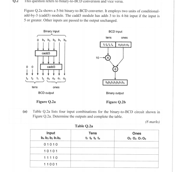
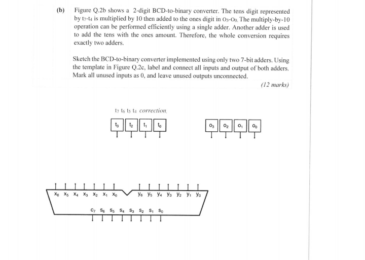
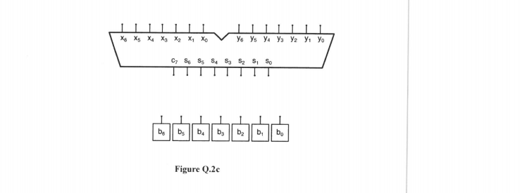
This question refers to binary-to-BCD conversion and vice versa. Figure Q.2a shows a 5-bit binary-to-BCD converter. It employs two units of conditional- add-by-3 (cadd3) module. The cadd3 module has adds 3 to its 4-bit input if the input is 5 or greater. Other inputs are passed to the output unchanged. Binary input o by by by b, bo BCD input tens ones 174140,0,0,00 cadd3 10 cadd3 to to totoo, 0, 0, 0, bob, b, b, b, b, b, tens ones BCD output Binary output Figure Q.2a Figure Q.25 (a) Table Q.2a lists four input combinations for the binary-to-BCD circuit shown in Figure Q.2a. Determine the outputs and complete the table. (8 marks) Table Q.2a Input Tens Ones be bg by bibo tz ts ts to O, O2 0,00 01010 10101 11110 11001 (b) Figure Q.2b shows a 2-digit BCD-to-binary converter. The tens digit represented by t7-ta is multiplied by 10 then added to the ones digit in 03-0. The multiply-by-10 operation can be performed efficiently using a single adder. Another adder is used to add the tens with the ones amount. Therefore, the whole conversion requires exactly two adders. Sketch the BCD-to-binary converter implemented using only two 7-bit adders. Using the template in Figure Q.2c, label and connect all inputs and output of both adders. Mark all unused inputs as 0, and leave unused outputs unconnected. (12 marks) ty to ts to correction 0990 Og O2 0 00 Xe X, X, X X X, Xo % , . C7 S S S S S S So X6 x x x x x xo III . . C S6 S S S S S SO | || . || . || | || . || Figure Q.2c This question refers to binary-to-BCD conversion and vice versa. Figure Q.2a shows a 5-bit binary-to-BCD converter. It employs two units of conditional- add-by-3 (cadd3) module. The cadd3 module has adds 3 to its 4-bit input if the input is 5 or greater. Other inputs are passed to the output unchanged. Binary input o by by by b, bo BCD input tens ones 174140,0,0,00 cadd3 10 cadd3 to to totoo, 0, 0, 0, bob, b, b, b, b, b, tens ones BCD output Binary output Figure Q.2a Figure Q.25 (a) Table Q.2a lists four input combinations for the binary-to-BCD circuit shown in Figure Q.2a. Determine the outputs and complete the table. (8 marks) Table Q.2a Input Tens Ones be bg by bibo tz ts ts to O, O2 0,00 01010 10101 11110 11001 (b) Figure Q.2b shows a 2-digit BCD-to-binary converter. The tens digit represented by t7-ta is multiplied by 10 then added to the ones digit in 03-0. The multiply-by-10 operation can be performed efficiently using a single adder. Another adder is used to add the tens with the ones amount. Therefore, the whole conversion requires exactly two adders. Sketch the BCD-to-binary converter implemented using only two 7-bit adders. Using the template in Figure Q.2c, label and connect all inputs and output of both adders. Mark all unused inputs as 0, and leave unused outputs unconnected. (12 marks) ty to ts to correction 0990 Og O2 0 00 Xe X, X, X X X, Xo % , . C7 S S S S S S So X6 x x x x x xo III . . C S6 S S S S S SO | || . || . || | || . || Figure Q.2c
Step by Step Solution
There are 3 Steps involved in it

Get step-by-step solutions from verified subject matter experts