

Question: This section will have students utilize a DC motor as well as an increas- ing number of other devices. Before we start using PWM for
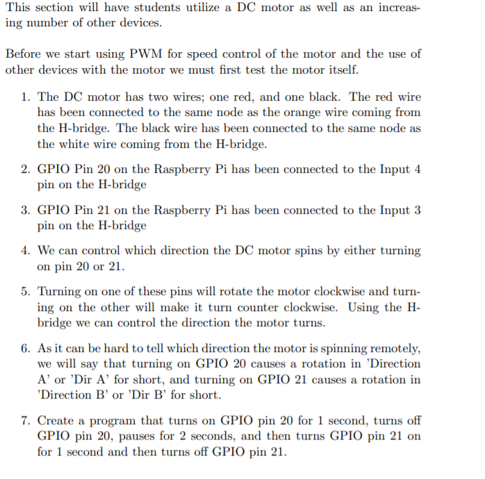
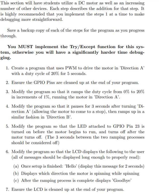
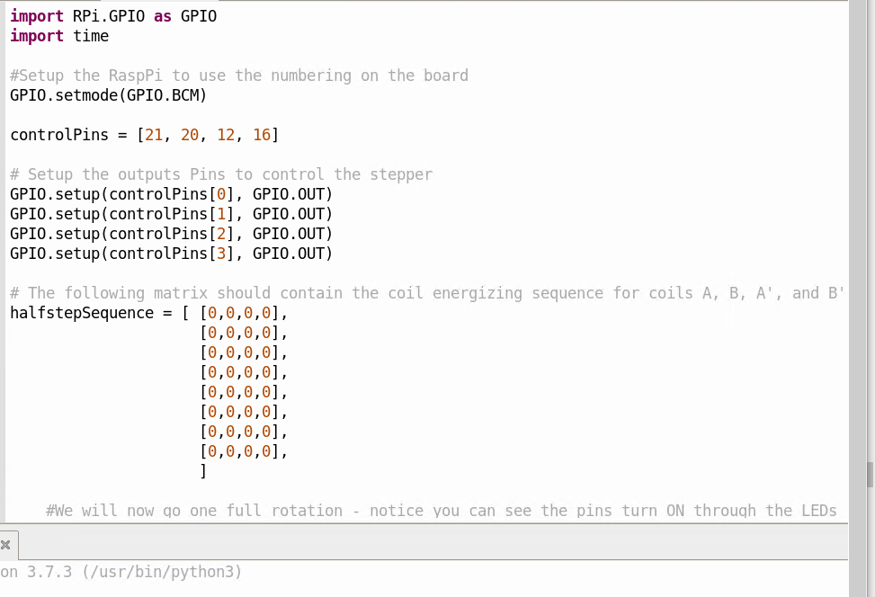
This section will have students utilize a DC motor as well as an increas- ing number of other devices. Before we start using PWM for speed control of the motor and the use of other devices with the motor we must first test the motor itself. 1. The DC motor has two wires; one red, and one black. The red wire has been connected to the same node as the orange wire coming from the H-bridge. The black wire has been connected to the same node as the white wire coming from the H-bridge. 2. GPIO Pin 20 on the Raspberry Pi has been connected to the Input 4 pin on the H-bridge 3. GPIO Pin 21 on the Raspberry Pi has been connected to the Input 3 pin on the H-bridge 4. We can control which direction the DC motor spins by either turning on pin 20 or 21. 5. Turning on one of these pins will rotate the motor clockwise and turn- ing on the other will make it turn counter clockwise. Using the H- bridge we can control the direction the motor turns. 6. As it can be hard to tell which direction the motor is spinning remotely, we will say that turning on GPIO 20 causes a rotation in 'Direction Aor 'Dir A' for short, and turning on GPIO 21 causes a rotation in 'Direction B' or 'Dir B' for short. 7. Create a program that turns on GPIO pin 20 for 1 second, turns off GPIO pin 20, pauses for 2 seconds, and then turns GPIO pin 21 on for 1 second and then turns off GPIO pin 21. This section will have students utilize a DC motor as well as an increasing number of other devices. Each step describes the addition for that step. It is highly recommended that you implement the steps 1 at a time to make debugging more straightforward. Save a backup copy of each of the steps for the program as you progress through You MUST implement the Try/Except function for this sys- tem, otherwise you will have a significantly harder time debug- ging. 1. Create a program that uses PWM to drive the motor in 'Direction A' with a duty cycle of 20% for 5 seconds. 2. Ensure the GPIO Pins are cleaned up at the end of your program. 3. Modify the program so that it ramps the duty cycle from 0% to 20% in increments of 1%, running the motor in 'Direction A'. 4. Modify the program so that it pauses for 3 seconds after turning 'Di- rection A' (allowing the motor to come to a stop), then ramps up in a similar fashion in 'Direction B. 5. Modify the program so that the LED attached to GPIO Pin 23 is turned on before the motor begins to run, and turns off after the motor turns off. (The 3 seconds between the two ramping processes should be considered off) 6. Modify the program so that the LCD displays the following to the user (all of messages should be displayed long enough to properly read): (a) Once setup is finished: 'Hello' (display this message for 2 seconds) (b) Displays which direction the motor is spinning while spinning (c) After the ramping process is complete displays 'Goodbye 7. Ensure the LCD is cleaned up at the end of your program. import RPi GPIO as GPIO import time #Setup the Rasppi to use the numbering on the board GPIO.setmode (GPIO.BCM) controlPins = [21, 20, 12, 16] # Setup the outputs Pins to control the stepper GPIO.setup(controlPins[0], GPIO.OUT) GPIO.setup(controlPins[1], GPIO.OUT) GPIO.setup(controlPins[2], GPIO.OUT) GPIO.setup(controlPins[3], GPIO.OUT) # The following matrix should contain the coil energizing sequence for coils A, B, A', and B' halfstepSequence = ( [0,0,0,0], [0,0,0,0], [0,0,0,0], [0,0,0,0], [0,0,0,0], [0,0,0,0], [0,0,0,0], [0,0,0,0], ] #We will now go one full rotation - notice you can see the pins turn ON through the LEDS x on 3.7.3 (/usr/bin/python3) This section will have students utilize a DC motor as well as an increas- ing number of other devices. Before we start using PWM for speed control of the motor and the use of other devices with the motor we must first test the motor itself. 1. The DC motor has two wires; one red, and one black. The red wire has been connected to the same node as the orange wire coming from the H-bridge. The black wire has been connected to the same node as the white wire coming from the H-bridge. 2. GPIO Pin 20 on the Raspberry Pi has been connected to the Input 4 pin on the H-bridge 3. GPIO Pin 21 on the Raspberry Pi has been connected to the Input 3 pin on the H-bridge 4. We can control which direction the DC motor spins by either turning on pin 20 or 21. 5. Turning on one of these pins will rotate the motor clockwise and turn- ing on the other will make it turn counter clockwise. Using the H- bridge we can control the direction the motor turns. 6. As it can be hard to tell which direction the motor is spinning remotely, we will say that turning on GPIO 20 causes a rotation in 'Direction Aor 'Dir A' for short, and turning on GPIO 21 causes a rotation in 'Direction B' or 'Dir B' for short. 7. Create a program that turns on GPIO pin 20 for 1 second, turns off GPIO pin 20, pauses for 2 seconds, and then turns GPIO pin 21 on for 1 second and then turns off GPIO pin 21. This section will have students utilize a DC motor as well as an increasing number of other devices. Each step describes the addition for that step. It is highly recommended that you implement the steps 1 at a time to make debugging more straightforward. Save a backup copy of each of the steps for the program as you progress through You MUST implement the Try/Except function for this sys- tem, otherwise you will have a significantly harder time debug- ging. 1. Create a program that uses PWM to drive the motor in 'Direction A' with a duty cycle of 20% for 5 seconds. 2. Ensure the GPIO Pins are cleaned up at the end of your program. 3. Modify the program so that it ramps the duty cycle from 0% to 20% in increments of 1%, running the motor in 'Direction A'. 4. Modify the program so that it pauses for 3 seconds after turning 'Di- rection A' (allowing the motor to come to a stop), then ramps up in a similar fashion in 'Direction B. 5. Modify the program so that the LED attached to GPIO Pin 23 is turned on before the motor begins to run, and turns off after the motor turns off. (The 3 seconds between the two ramping processes should be considered off) 6. Modify the program so that the LCD displays the following to the user (all of messages should be displayed long enough to properly read): (a) Once setup is finished: 'Hello' (display this message for 2 seconds) (b) Displays which direction the motor is spinning while spinning (c) After the ramping process is complete displays 'Goodbye 7. Ensure the LCD is cleaned up at the end of your program. import RPi GPIO as GPIO import time #Setup the Rasppi to use the numbering on the board GPIO.setmode (GPIO.BCM) controlPins = [21, 20, 12, 16] # Setup the outputs Pins to control the stepper GPIO.setup(controlPins[0], GPIO.OUT) GPIO.setup(controlPins[1], GPIO.OUT) GPIO.setup(controlPins[2], GPIO.OUT) GPIO.setup(controlPins[3], GPIO.OUT) # The following matrix should contain the coil energizing sequence for coils A, B, A', and B' halfstepSequence = ( [0,0,0,0], [0,0,0,0], [0,0,0,0], [0,0,0,0], [0,0,0,0], [0,0,0,0], [0,0,0,0], [0,0,0,0], ] #We will now go one full rotation - notice you can see the pins turn ON through the LEDS x on 3.7.3 (/usr/bin/python3)
Step by Step Solution
There are 3 Steps involved in it

Get step-by-step solutions from verified subject matter experts