

Question: To draw the sequence network diagram for the given system and indicate the per unit (p.u.) reactance values, we'll use the following information and
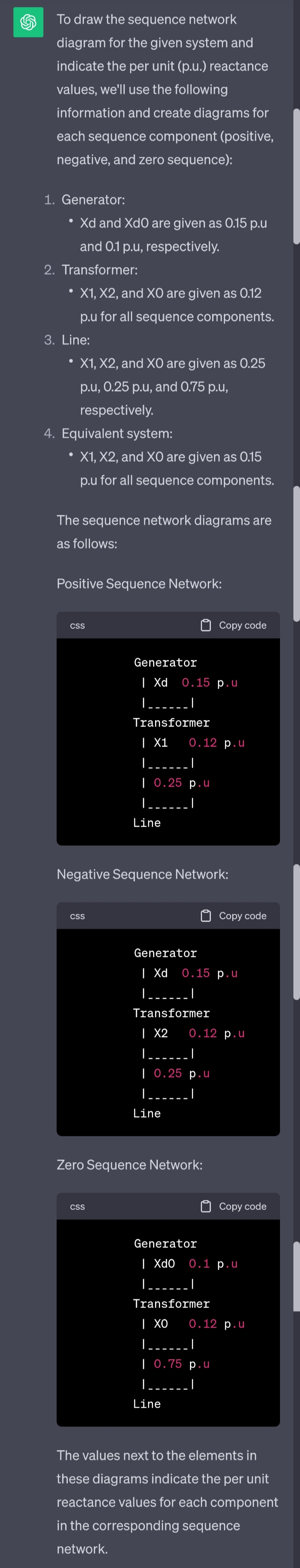
To draw the sequence network diagram for the given system and indicate the per unit (p.u.) reactance values, we'll use the following information and create diagrams for each sequence component (positive, negative, and zero sequence): 1. Generator: . Xd and Xdo are given as 0.15 p.u and 0.1 p.u, respectively. 2. Transformer: X1, X2, and XO are given as 0.12 p.u for all sequence components. 3. Line: X1, X2, and XO are given as 0.25 p.u, 0.25 p.u, and 0.75 p.u, respectively. 4. Equivalent system: X1, X2, and XO are given as 0.15 p.u for all sequence components. The sequence network diagrams are as follows: Positive Sequence Network: CSS Copy code Generator | Xd 0.15 p.u Transformer | X1 0.12 p.u | 0.25 p.u Line Negative Sequence Network: CSS Copy code Generator | Xd 0.15 p.u Transformer | X2 0.12 p.u | | 0.25 p.u Line Zero Sequence Network: CSS Copy code Generator | Xdo 0.1 p.u Transformer | XO 0.12 p.u | | 0.75 p.u | _. Line The values next to the elements in these diagrams indicate the per unit reactance values for each component in the corresponding sequence network.
Step by Step Solution
There are 3 Steps involved in it

Get step-by-step solutions from verified subject matter experts