

Question: To implement a 5~67 counter that counts 5,6, , 66, 67 and then repeats the cycle by using two 74x163s in LogicWorks 5, where each
To implement a 5~67 counter that counts 5,6, , 66, 67 and then repeats the cycle by using two 74x163s in LogicWorks 5, where each 74x163 counter unit is to be first made a BCD counter.
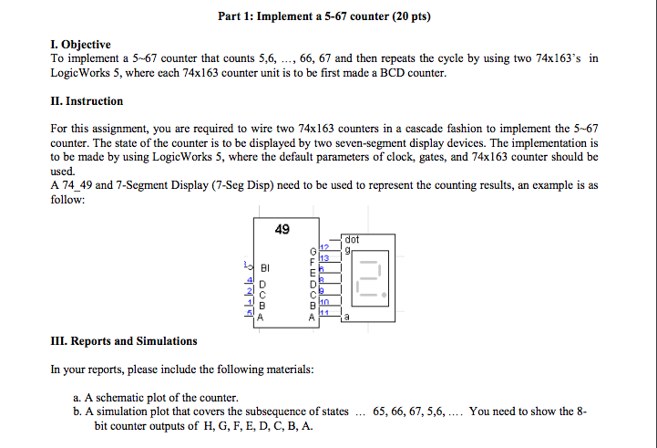
Part 1: Implement a 5-67 counter (20 pts) I. Objective To implement a 5-67 counter that counts 5,6 66, 67 and then repeats the cycle by using two 74x163 in LogicWorks 5, where each 74x163 counter unit is to be first made a BCD counter. II. Instruction For this assignment, you are required to wire two 74x163 counters in a cascade fashion to implement the 5-67 counter. The state of the counter is to be displayed by two seven-segment display devices. The implementation is to be made by using LogicWorks 5, where the default parameters of clock, gates, and 74x163 counter should be used. A 74 49 and 7-Segment Display (7-Seg Disp) need to be used to represent the counting results, an example is as follow: 49 III. Reports and Simulations In your reports, please include the following materials a. A schematic plot of the counter. b. A simulation plot that covers the subsequence of states 65, 66, 67, 5,6, You need to show the 8 bit counter outputs of H, G, F, E, D, C, B, A. Part 1: Implement a 5-67 counter (20 pts) I. Objective To implement a 5-67 counter that counts 5,6 66, 67 and then repeats the cycle by using two 74x163 in LogicWorks 5, where each 74x163 counter unit is to be first made a BCD counter. II. Instruction For this assignment, you are required to wire two 74x163 counters in a cascade fashion to implement the 5-67 counter. The state of the counter is to be displayed by two seven-segment display devices. The implementation is to be made by using LogicWorks 5, where the default parameters of clock, gates, and 74x163 counter should be used. A 74 49 and 7-Segment Display (7-Seg Disp) need to be used to represent the counting results, an example is as follow: 49 III. Reports and Simulations In your reports, please include the following materials a. A schematic plot of the counter. b. A simulation plot that covers the subsequence of states 65, 66, 67, 5,6, You need to show the 8 bit counter outputs of H, G, F, E, D, C, B, A
Step by Step Solution
There are 3 Steps involved in it

Get step-by-step solutions from verified subject matter experts