

Question: undefined Consider the sequential circuit implementing a serial adder built with a 1-bit full adder and a D flip-flop (Fig P5.7 on page 246 of
 undefined
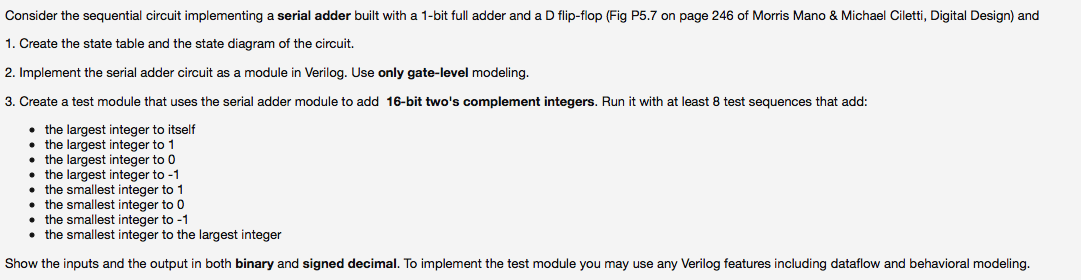
Consider the sequential circuit implementing a serial adder built with a 1-bit full adder and a D flip-flop (Fig P5.7 on page 246 of Morris Mano & Michael Ciletti, Digital Design) and 1. Create the state table and the state diagram of the circuit. 2. Implement the serial adder circuit as a module in Verilog. Use only gate-level modeling. 3. Create test module that uses the serial adder module to add 16-bit two's complement integers. Run it with at least 8 test sequences that add: the largest integer to itself the largest integer to 1 the largest integer to O the largest integer to -1 the smallest integer to 1 the smallest integer to O the smallest integer to -1 the smallest integer to the largest integer Show the inputs and the output in both binary and signed decimal. To implement the test module you may use any Verilog features including dataflow and behavioral modeling
Step by Step Solution
There are 3 Steps involved in it

Get step-by-step solutions from verified subject matter experts