

Question: use omron cj2m program Table 2 shows the sequence of the lighting system. The system works when SELECTOR in AUTO Mode (logic 1). For the
 use omron cj2m program
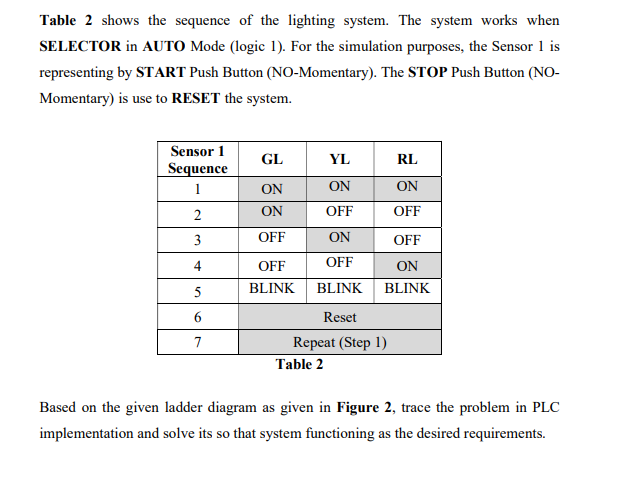
Table 2 shows the sequence of the lighting system. The system works when SELECTOR in AUTO Mode (logic 1). For the simulation purposes, the Sensor 1 is representing by START Push Button (NO-Momentary). The STOP Push Button (NO- Momentary) is use to RESET the system. GL YL RL Sensor 1 Sequence 1 ON ON ON ON OFF 2 OFF 3 4 OFF ON OFF OFF OFF ON BLINK BLINK BLINK 5 6 7 Reset Repeat (Step 1) Table 2 Based on the given ladder diagram as given in Figure 2, trace the problem in PLC implementation and solve its so that system functioning as the desired requirements
Step by Step Solution
There are 3 Steps involved in it
1 Expert Approved Answer
Step: 1 Unlock

Question Has Been Solved by an Expert!
Get step-by-step solutions from verified subject matter experts
Step: 2 Unlock
Step: 3 Unlock