

Question: The absolute addresses for inputs / outputs are given as in the picture on the right: 1 2 . 0 : Digital input bit connected
The absolute addresses for inputsoutputs are given as
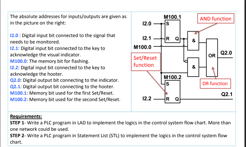
in the picture on the right:
: Digital input bit connected to the signal that
needs to be monitored.
: Digital input bit connected to the key to
acknowledge the visual indicator.
M: The memory bit for flashing.
: Digital input bit connected to the key to
acknowledge the hooter.
Q: Digital output bit connecting to the indicator.
Q: Digital output bit connecting to the hooter.
M: Memory bit used for the first SetReset
M: Memory bit used for the second SetReset
Requirements:
STEP Write a PLC program in LAD to implement the logics in the control system flow chart. More than
one network could be used.
STEP Write a PLC program in Statement List STL to implement the logics in the control system flow
chart.
Step by Step Solution
There are 3 Steps involved in it
1 Expert Approved Answer
Step: 1 Unlock

Question Has Been Solved by an Expert!
Get step-by-step solutions from verified subject matter experts
Step: 2 Unlock
Step: 3 Unlock