

Question: USE SOLIDWORKS Exercise 5 . 1 7 : 3 D SKETCH / HOLE WIZARD Create a part using the Hole Wizard feature. Apply the 3
USE SOLIDWORKS Exercise : D SKETCHHOLE WIZARD
Create a part using the Hole Wizard feature. Apply the D
sketch placement method as illustrated in the FeatureManager.
Insert and dimension a hole on a cylindrical face.
Copy and open the Hole Wizard model from the Chapter
Homework folder.
Click the Hole Wizard Features tool. The Hole Specification
PropertyManager is displayed.
Create a Counterbore, ANSI Inch, Socket Head Cap Screw
fastener Type. Size Fit Normal. End Condition
Through All with a in Head clearance.
Click the Positions Tab.
Click the D Sketch button. The Hole Position PropertyManager is
displayed. SOLIDWORKS displays an active D interface with the
Point tool. When the Point tool is
active, wherever you click, you will create a
point.
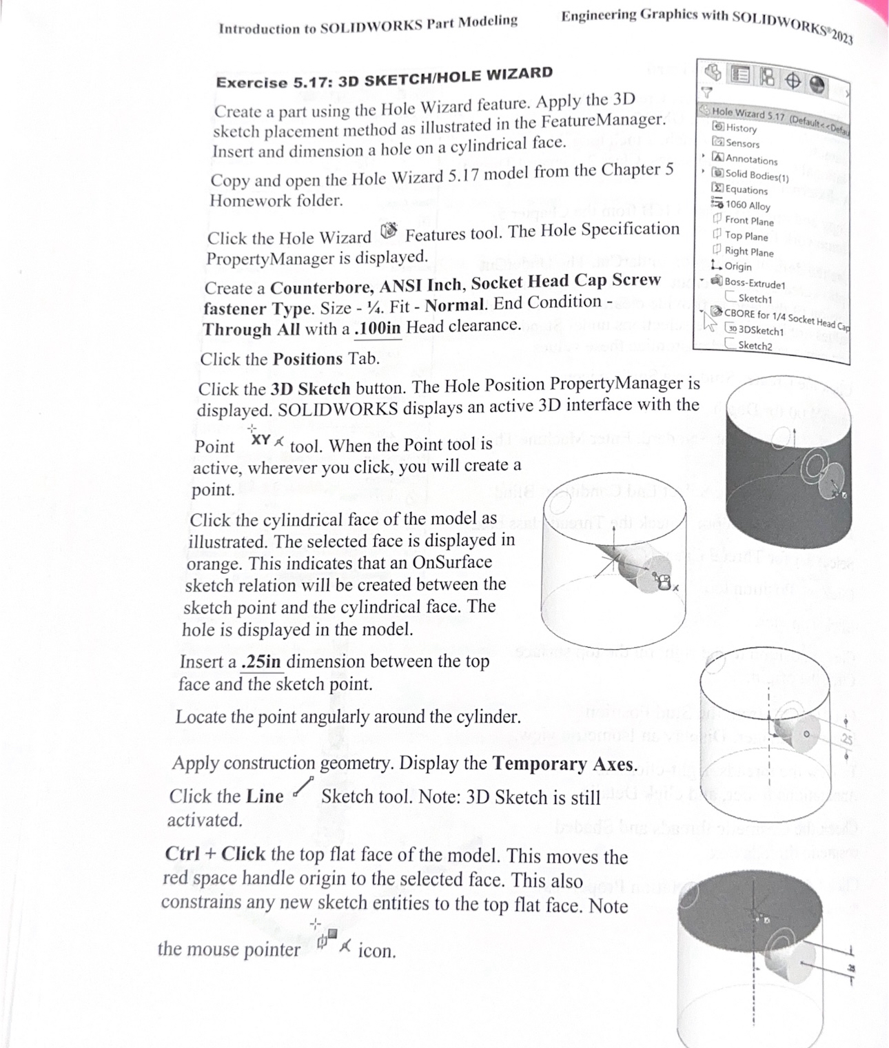
Click the cylindrical face of the model as
illustrated. The selected face is displayed in
orange. This indicates that an OnSurface
sketch relation will be created between the
sketch point and the cylindrical face. The
hole is displayed in the model.
Insert a in dimension between the top
face and the sketch point.
Locate the point angularly around the cylinder.
Apply construction geometry. Display the Temporary Axes.
Click the Line Sketch tool. Note: D Sketch is still
activated.
Ctrl Click the top flat face of the model. This moves the
red space handle origin to the selected face. This also
constrains any new sketch entities to the top flat face. Note
the mouse pointer
Step by Step Solution
There are 3 Steps involved in it
1 Expert Approved Answer
Step: 1 Unlock

Question Has Been Solved by an Expert!
Get step-by-step solutions from verified subject matter experts
Step: 2 Unlock
Step: 3 Unlock