

Question: Use the MICROWIND software and its companion the DSCH software to perform the following: (a) Draw a schematic circuit diagram for the charge-redistribution serial
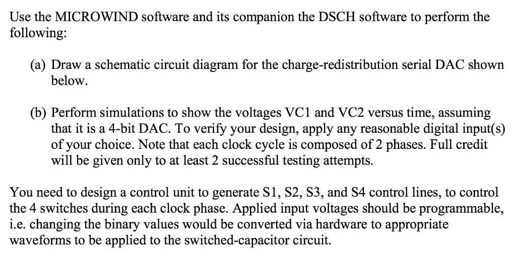
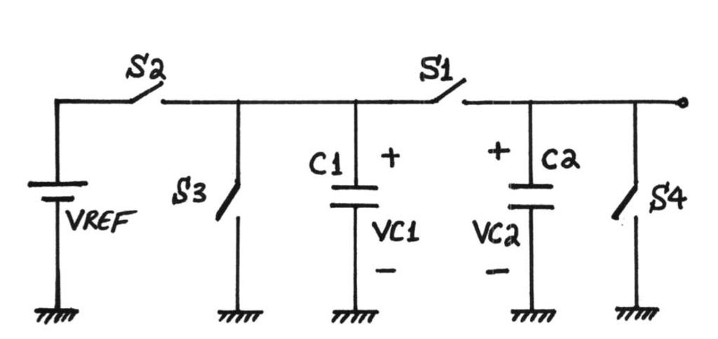
Use the MICROWIND software and its companion the DSCH software to perform the following: (a) Draw a schematic circuit diagram for the charge-redistribution serial DAC shown below. (b) Perform simulations to show the voltages VC1 and VC2 versus time, assuming that it is a 4-bit DAC. To verify your design, apply any reasonable digital input(s) of your choice. Note that each clock cycle is composed of 2 phases. Full credit will be given only to at least 2 successful testing attempts. You need to design a control unit to generate S1, S2, S3, and S4 control lines, to control the 4 switches during each clock phase. Applied input voltages should be programmable, i.e. changing the binary values would be converted via hardware to appropriate waveforms to be applied to the switched-capacitor circuit. Sa St C1 + + 3 TVREF VC1 VC2 - -
Step by Step Solution
There are 3 Steps involved in it

Get step-by-step solutions from verified subject matter experts