

Question: Using 95% reliability, repeat problem 4.4, but now use the AGMA method to determine both the bending and contact (surface) fatigue factors of safety
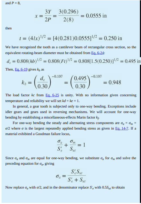
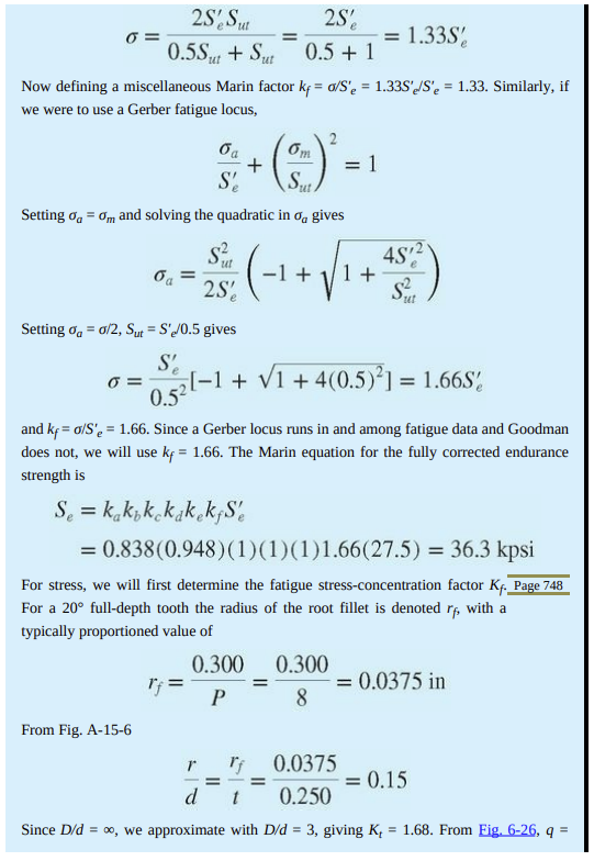
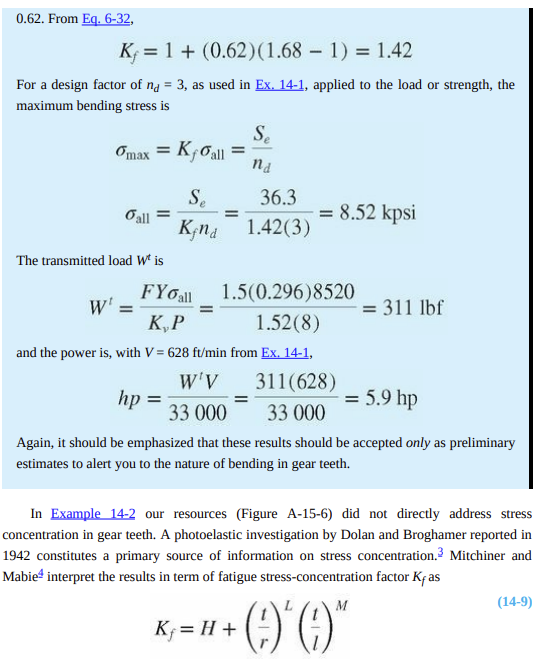
Using 95% reliability, repeat problem 4.4, but now use the AGMA method to determine both the bending and contact (surface) fatigue factors of safety for the pinion and the gear. State all assumptions and be sure to reflect on how answers to 4.4 and 4.5 compare and which you think is more conservative and which is more accurate. A spur gear reducer has a 20-tooth pinion driven by a 1200 rpm electric motor and a 38-tooth gear that drives a load. The system is designed to run 5 days/week, 8 hours/day for 5 years. The transmitted load, Wt is 3700 Newtons. It is proposed that standard 20 full-depth gears be used, with both pinion and gear teeth being cut with a low-cost, average quality, form-cutting process from steel of 235 Brinell hardness for the gear and 260 Brinell hardness for the pinion (see equation 2-21 to estimate ultimate strength). The module of the gears is 2.5 and the face width is 25 mm. Using the Goodman approach of Chapter 6, which is similar to, but not exactly the same as Example 14-2, estimate the reliability for a factor of safety of 1 with respect to bending fatigue failure of both the gear and the pinion. Use a Marin factor Kf= 1, not 1.66 as in Example 14.2, and the modified Goodman approach for fluctuating stress. Also, estimate the stress concentration factor using Figure A-15-6 as was done in Example 14.2. In your reflection compare this to the Kf you would get from equation 14-9. EXAMPLE 14-2 Estimate the horsepower rating of the gear in the previous example based on obtaining an infinite life in bending. Solution The rotating-beam endurance limit is estimated from Eq. 6-10, S'e = 0.5Sut = 0.5(55) = 27.5 kpsi To obtain the surface finish Marin factor ka we refer to Table 6-3 for machined surface, finding a = 2.00 and b = -0.217. Then Eq. 6-18 gives the surface finish Marin factor ka as ka = as = 2.00(55)- = 0.838 The next step is to estimate the size factor kb. From Table 13-1, the sum of the addendum and dedendum is 1 1.25 1 1.25 = + 8 P 8 The tooth thickness t in Fig. 14-1b is given in Sec. 14-1 [Eq. (b)] as t = when x = 3Y/(2P) from Eq. 14-3. Therefore, since from Ex. 14-1 Y = 0.296 + = 0.281 in = (41x)1/2 Page 747 and P = 8, then kt X = = 3Y 3(0.296) 2(8) 2P 1 = (41x)/ = [4(0.281)0.05551/ = 0.250 in We have recognized the tooth as a cantilever beam of rectangular cross section, so the equivalent rotating-beam diameter must be obtained from Eq. 6-24: de = 0.808(hb)/2 = 0.808(Ft)/2 = 0.808[1.5(0.250)]/2 = 0.495 in Then, Eq. 6-19 gives k, as = de 0.30 -0.107 = 0.0555 in = 0.495 0.30 -0.107 6m oa + = 1 S' ut = 0.948 The load factor kc from Eq. 6-25 is unity. With no information given concerning temperature and reliability we will set kd = ke = 1. In general, a gear tooth is subjected only to one-way bending. Exceptions include idler gears and gears used in reversing mechanisms. We will account for one-way bending by establishing a miscellaneous-effects Marin factor kf. For one-way bending the steady and alternating stress components are og = m = o/2 where o is the largest repeatedly applied bending stress as given in Eq. 14-7. If a material exhibited a Goodman failure locus, Since og and om are equal for one-way bending, we substitute o for om and solve the preceding equation for %, giving S'e Sut S'e + Sut Now replaced with o/2, and in the denominator replace S'e with 0.55ut to obtain 2S' Sut 0.5Sut + Sut Now defining a miscellaneous Marin factor kf = a/S'e = 1.33S'e/S'e = 1.33. Similarly, if we were to use a Gerber fatigue locus, 6 = 0 = oa S' oa = 5m Sut Setting %a = om and solving the quadratic in o gives From Fig. A-15-6 + Se = kakok kakekfS d = 6, 2S' 0.5 + 1 2 ut -S (-1 + +45 2) 1 2S ut Setting % = 0/2, Sut = S'e/0.5 gives S' 0.5 and kf=o/S'e = 1.66. Since a Gerber locus runs in and among fatigue data and Goodman does not, we will use kf = 1.66. The Marin equation for the fully corrected endurance strength is = = = 1 [-1 + 1 +4(0.5)] = 1.66S = 1.33S = 0.838 (0.948)(1)(1)(1)1.66(27.5) = 36.3 kpsi For stress, we will first determine the fatigue stress-concentration factor Kf. Page 748 For a 20 full-depth tooth the radius of the root fillet is denoted rf, with a typically proportioned value of 0.300 0.300 P 8 = 0.0375 in r 0.0375 d 0.250 Since D/d = , we approximate with D/d = 3, giving K, = 1.68. From Fig. 6-26, q = = 0.15 0.62. From Eq. 6-32, K 1+ (0.62) (1.68 - 1) = 1.42 For a design factor of na = 3, as used in Ex. 14-1, applied to the load or strength, the maximum bending stress is omax = Kfall Se Kfnd Gall = The transmitted load Wt is = W' = Se nd 36.3 1.42(3) FYo all K,P and the power is, with V=628 ft/min from Ex. 14-1, W'V 311(628) hp = 5.9 hp 33 000 33 000 Again, it should be emphasized that these results should be accepted only as preliminary estimates to alert you to the nature of bending in gear teeth. = = 8.52 kpsi 1.5(0.296)8520 1.52(8) Kf = H + In Example 14-2 our resources (Figure A-15-6) did not directly address stress concentration in gear teeth. A photoelastic investigation by Dolan and Broghamer reported in 1942 constitutes a primary source of information on stress concentration. Mitchiner and Mabie interpret the results in term of fatigue stress-concentration factor Kas M + )*(* = 311 lbf (14-9)
Step by Step Solution
There are 3 Steps involved in it

Get step-by-step solutions from verified subject matter experts