

Question: = Using D flip-flops and NAND gates, design a Moore finite state machine with one input x and one output z. When x = 1,
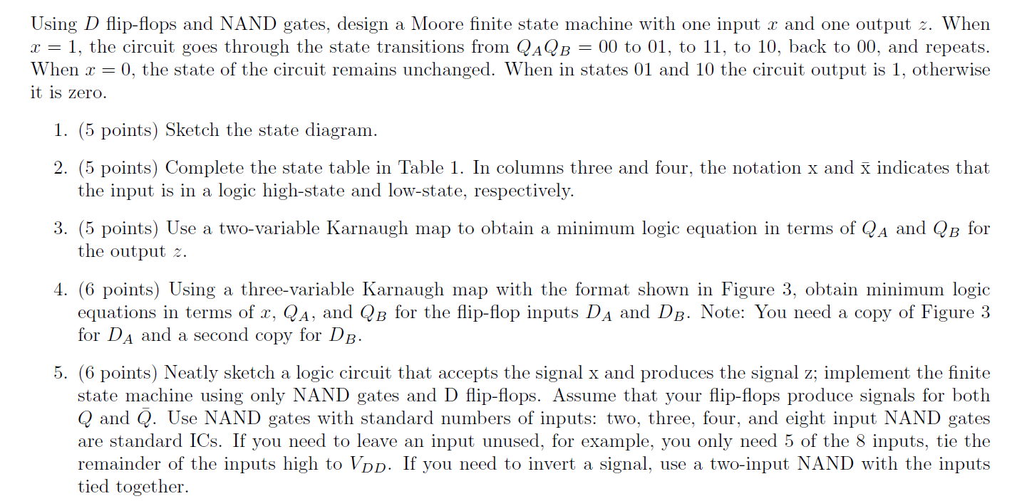
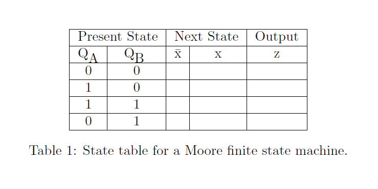
= Using D flip-flops and NAND gates, design a Moore finite state machine with one input x and one output z. When x = 1, the circuit goes through the state transitions from QAQB 00 to 01, to 11, to 10, back to 00, and repeats. When x = 0, the state of the circuit remains unchanged. When in states 01 and 10 the circuit output is 1, otherwise it is zero. 1. (5 points) Sketch the state diagram. 2. (5 points) Complete the state table in Table 1. In columns three and four, the notation x and x indicates that the input is in a logic high-state and low-state, respectively. 3. (5 points) Use a two-variable Karnaugh map to obtain a minimum logic equation in terms of QA and QB for the output 2. 4. (6 points) Using a three-variable Karnaugh map with the format shown in Figure 3, obtain minimum logic equations in terms of x, QA, and QB for the flip-flop inputs DA and DB. Note: You need a copy of Figure 3 for DA and a second copy for DB. 5. (6 points) Neatly sketch a logic circuit that accepts the signal x and produces the signal z; implement the finite state machine using only NAND gates and D flip-flops. Assume that your flip-flops produce signals for both Q and Q. Use NAND gates with standard numbers of inputs: two, three, four, and eight input NAND gates are standard ICs. If you need to leave an input unused, for example, you only need 5 of the 8 inputs, tie the remainder of the inputs high to Vpd. If you need to invert a signal, use a two-input NAND with the inputs tied together. Next State Output z X X Present State QA QB 0 0 1 0 1 1 0 1 Table 1: State table for a Moore finite state machine
Step by Step Solution
There are 3 Steps involved in it

Get step-by-step solutions from verified subject matter experts