

Question: Using Datum Planes Create the part shown in the image using the given dimensions. As you create the part, you must create a datum plane
Using Datum Planes
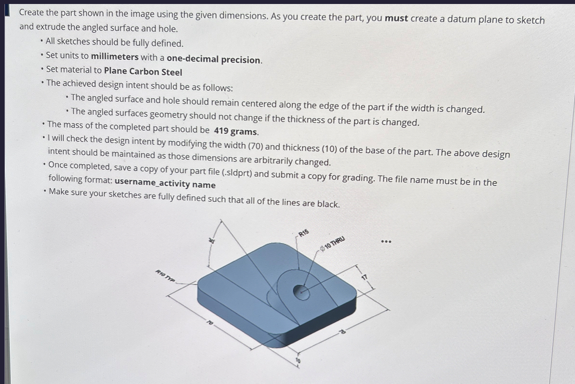
Create the part shown in the image using the given dimensions. As you create the part, you must create a datum plane to sketch
and extrude the angled surface and hole.
All sketches should be fully defined.
Set units to millimeters with a onedecimal precision.
Set material to Plane Carbon Steel
The achieved design intent should be as follows:
The angled surface and hole should remain centered along the edge of the part if the width is changed.
The angled surfaces geometry should not change if the thickness of the part is changed.
The mass of the completed part should be grams.
I will check the design intent by modifying the width and thickness of the base of the part. The above design
intent should be maintained as those dimensions are arbitrarily changed.
Once completed, save a copy of your part file sldprt and submit a copy for grading. The file name must be in the
following format: usernameactivity name
Make sure your sketches are fully defined such that all of the lines are black.
Step by Step Solution
There are 3 Steps involved in it
1 Expert Approved Answer
Step: 1 Unlock

Question Has Been Solved by an Expert!
Get step-by-step solutions from verified subject matter experts
Step: 2 Unlock
Step: 3 Unlock