

Question: Using Multisim Workbench, design an ALU with 2 inputs A and B where both are 4 bits, 3 control inputs: M for mode selection,
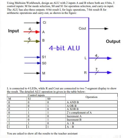
Using Multisim Workbench, design an ALU with 2 inputs A and B where both are 4 bits, 3 control inputs: M for mode selection, SO and S1 for operation selection, and carry-in input. The ALU has also three outputs: 4-bit result L for logic operations, 7-bit result R for arithmetic operations and carry-out, as shown in the figure: Input M 0 0 0 0 1 I 0 1 I Ci 0 0 I A B S1 SO M L is connected to 4 LEDs, while R and Cout are connected to two 7-segment display to show the result. The detailed ALU operation in given in the table below: Control inputs SI 0 4-bit ALU SO 0 1 0 1 0 1 0 Cout A AND B A OR B A XOR B A+B A-B L You are asked to show all the results to the teacher assistant R 2's complement of A Increment A Increment B Operation Output Using Multisim Workbench, design an ALU with 2 inputs A and B where both are 4 bits, 3 control inputs: M for mode selection, SO and S1 for operation selection, and carry-in input. The ALU has also three outputs: 4-bit result L for logic operations, 7-bit result R for arithmetic operations and carry-out, as shown in the figure: Input M 0 0 0 0 1 I 0 1 I Ci 0 0 I A B S1 SO M L is connected to 4 LEDs, while R and Cout are connected to two 7-segment display to show the result. The detailed ALU operation in given in the table below: Control inputs SI 0 4-bit ALU SO 0 1 0 1 0 1 0 Cout A AND B A OR B A XOR B A+B A-B L You are asked to show all the results to the teacher assistant R 2's complement of A Increment A Increment B Operation Output
Step by Step Solution
3.38 Rating (157 Votes )
There are 3 Steps involved in it
providing guidance on how to design the ALU in Multisim Workbench but I cant directly generate or di... View full answer

Get step-by-step solutions from verified subject matter experts