Question: using point form explain in short the main source function that enable transformation of the informatiom from the master to the skave in the Aruduino

 using point form explain in short the main source function that
enable transformation of the informatiom from the master to the skave in
the Aruduino ? note you have to explani in point for both
using point form explain in short the main source function that enable transformation of the informatiom from the master to the skave in the Aruduino ? note you have to explani in point for both the master and the slave

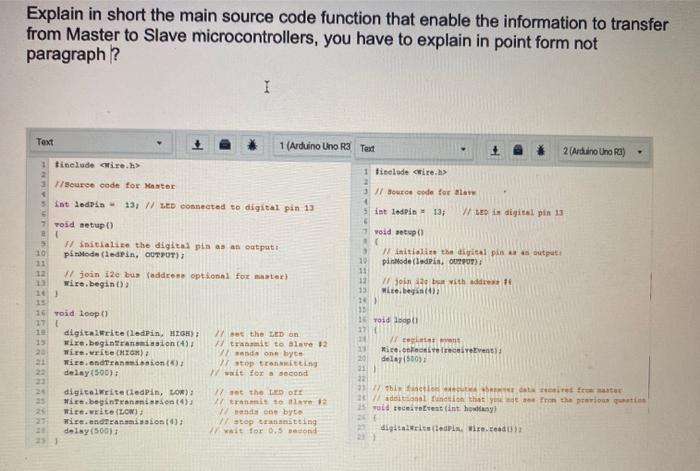
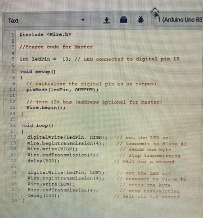
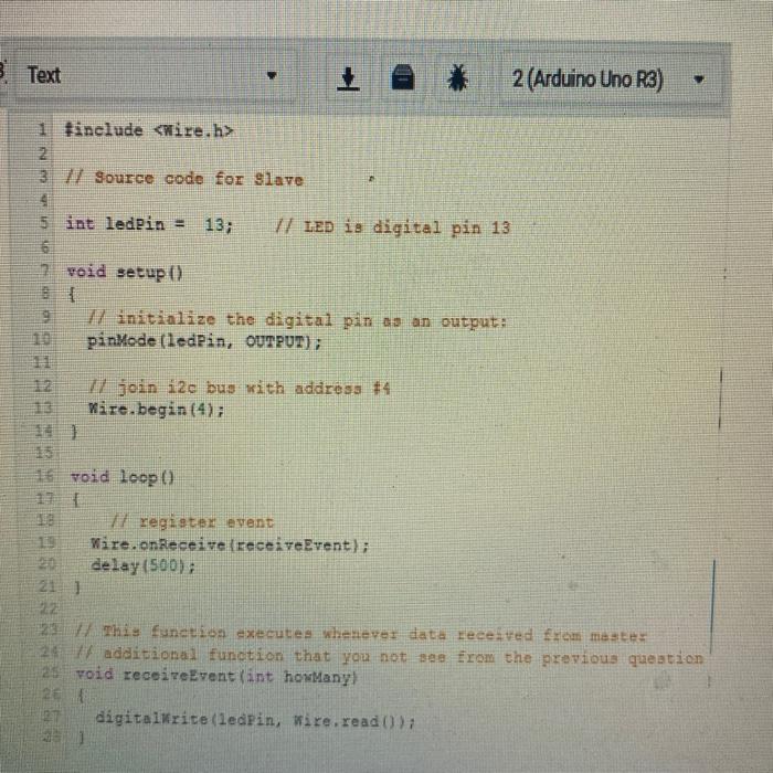
Explain in short the main source code function that enable the information to transfer from Master to Slave microcontrollers, you have to explain in point form not paragraph? Text 1 (Arduino Uno R3 Test 2 (Arduino Uno Ra) 1 tinclude cire.h> 1 source code for Master int ledrin 13; // LED Connected to digital pin 13 Tisclude tire.h> 11 source code for alar int ledPin 13; W LED i digital pin 13 void setup void setup() 3 10 13 12 # Initialize the digital pis as an output piroda (ledPin, OUTPUT) #join ile bu address optional for master) wire.begin() 3 Initialize the digital pln output 10 pinMode(ledPin, OUTPUT) 11 12 I join 12 with address 15 wice.be 152 13 1 Toid loopt! 16 Toid loop() 17 digitalWrite(ledPin, HIGH) wire.beginTransalon (4) wie.write CHIO) wire.andreanainnion () delay(500) 25 digitalWrite(ledPin, LOR) Wire.beginTransmission) mite.weite (LON) Wire.ndtransmission) delay(500); // set the LED on 17 Trit te Slave 92 and one byte Vstop tromitting wait for a second 1 W ten 20 Mirellevants 20 delay(500) 21 23 27this fictional free 2 dl function that you see from the previous qui od trentint howlany t the LED OTE tranmis 17 do byt Vstopitting wait for 0.5 Bond digitaliserin. Wien. Text * 1 (Arduino Uno R3 1 #include 2 3 //Source code for Master 4 sint ledPin = 13; // LED connected to digital pin 13 6 7 void etup() { 9 7/ initialize the digital pin as an output: pinMode(ledPin, OUTPUT); 11 12 77 join i2c bus (address optional for master) Wire.begin(); 14] HE WIN 15 D 16 void loop() { 18 digitalWrite(ledPin, HIGH); Wire.beginTransmission (4); 20 Wire.write (HIGH); 21 Wire.endTransmission (4); delay(50073 set the LED on transmit to slave #2 1 sends one byte 77 stop transmitting 77 wait for a second digitalWrite(ledPin, LOW); 25 Wire.beginTransmission (4); Wire.write (LOW); 27 Wire.endTransmission (4); 28 delay(500); 29 ) set the LED off transmit to Slave #2 77 senda one byte Vstop transmitting 7 Wait for 15 second B Text 2 (Arduino Uno R3) 1 Hinclude 2 2 37 Source code for Slave 4 5 int ledPin = 13; V/ LED is digital pin 13 6 void setup() 9 17 initialize the digital pin as an output: pinMode(ledPin, OUTPUT); 17 join i2e bus with address #4 Wire.begin(4); 16 void loop register event Wire.on Receive receiveEvent); delay(500); 21 ] This function executes whenever data received from master 24 / additional function that you not see from the previous question 25 void receiveEvent (int howManyl 26 27 digitalWrite(ledPin, wire.read()

Step by Step Solution

There are 3 Steps involved in it

1 Expert Approved Answer
Step: 1 Unlock blur-text-image
Question Has Been Solved by an Expert!

Get step-by-step solutions from verified subject matter experts

Step: 2 Unlock
Step: 3 Unlock

Students Have Also Explored These Related Databases Questions!