

Question: Using simulink, solve part A The current I, flowing through the circuit shown in figure P16.2, can be described by a second order ODE: d^2I/dt^2
Using simulink, solve part A
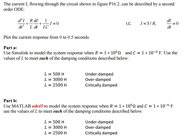
The current I, flowing through the circuit shown in figure P16.2, can be described by a second order ODE: d^2I/dt^2 + R dI/dt + 1/LC I = 0 I.C. I = 5/R, dI/dT = 0 Plot the current response from 0 to 0.5 seconds. Use Simulink to model the system response when R = 1 * 10^5 Ohm and C = 1 * 10^-6 F. Use the values of L to meet each of the damping conditions described below: L = 500 H Under-damped L = 3000 H Over-damped L = 2500 H Critically damped Use MATLAB ode45 to model the system response when R = 1 * 10^5 Ohm and C = 1 * 10^-6 F. use the values of L to meet each of the damping conditions described below: L = 500 H Under-damped L = 3000 H Over-damped L = 2500 H Critically damped The current I, flowing through the circuit shown in figure P16.2, can be described by a second order ODE: d^2I/dt^2 + R dI/dt + 1/LC I = 0 I.C. I = 5/R, dI/dT = 0 Plot the current response from 0 to 0.5 seconds. Use Simulink to model the system response when R = 1 * 10^5 Ohm and C = 1 * 10^-6 F. Use the values of L to meet each of the damping conditions described below: L = 500 H Under-damped L = 3000 H Over-damped L = 2500 H Critically damped Use MATLAB ode45 to model the system response when R = 1 * 10^5 Ohm and C = 1 * 10^-6 F. use the values of L to meet each of the damping conditions described below: L = 500 H Under-damped L = 3000 H Over-damped L = 2500 H Critically damped
Step by Step Solution
There are 3 Steps involved in it

Get step-by-step solutions from verified subject matter experts