

Question: Using VHDL language, ALTERA Quartus II software and ALTERA DE2-115 board, you should design, simulate and implement an 8-bit ALU circuit. This circuit will take
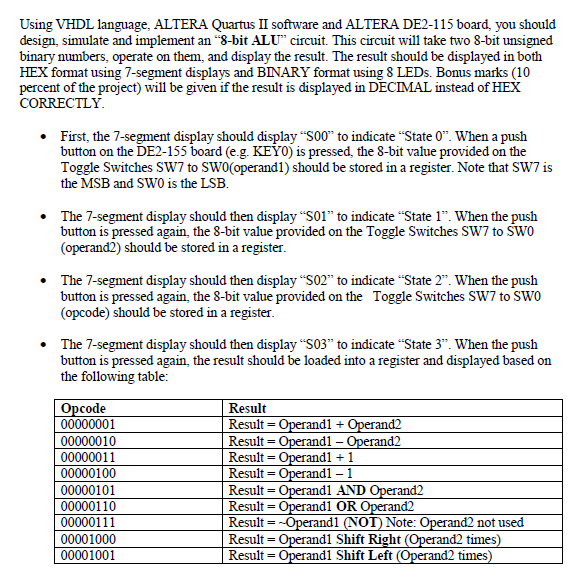
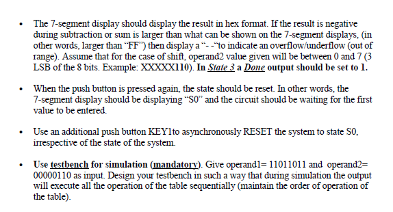
Using VHDL language, ALTERA Quartus II software and ALTERA DE2-115 board, you should design, simulate and implement an "8-bit ALU" circuit. This circuit will take two 8-bit unsigned binary numbers, operate on them, and display the result. The result should be displayed in both HEX format using 7-segment displays and BINARY format using 8 LEDs. Bonus marks (10 percent of the project) will be given if the result is displayed in DECIMAL instead of HEX CORRECTLY First, the 7-segment display should display "S00" to indicate "State 0". When a push button on the DE2-155 board (e.g. KEY0) is pressed, the 8-bit value provided on the Toggle Switches SW7 to SWo(operand1) should be stored in a register. Note that SW7 is the MSB and SW0 is the LSB. . The 7-segment display should then display S01" to indicate "State 1". When the push button is pressed again, the 8-bit value provided on the Toggle Switches SW7 to SW0 (operand2) should be stored in a register . The 7-segment display should then display S02" to indicate "State 2". When the push button is pressed again, the 8-bit value provided on the Toggle Switches SW7 to SWO (opcode) should be stored in a register The 7-segment display should then display S03" to indicate "State 3". When the push button is pressed again, the result should be loaded into a register and displayed based on the following table Result Result- Result- Result Result- Result Result Result- Result- code andi- andl 1 and1 1 00000010 00000011 00000100 00000101 00000110 00000111 00001000 00001001 d2 d1 AND d1 OR d2 not used d2 times) d1 Shift Right It- Operandl Shift Left erand2 times Using VHDL language, ALTERA Quartus II software and ALTERA DE2-115 board, you should design, simulate and implement an "8-bit ALU" circuit. This circuit will take two 8-bit unsigned binary numbers, operate on them, and display the result. The result should be displayed in both HEX format using 7-segment displays and BINARY format using 8 LEDs. Bonus marks (10 percent of the project) will be given if the result is displayed in DECIMAL instead of HEX CORRECTLY First, the 7-segment display should display "S00" to indicate "State 0". When a push button on the DE2-155 board (e.g. KEY0) is pressed, the 8-bit value provided on the Toggle Switches SW7 to SWo(operand1) should be stored in a register. Note that SW7 is the MSB and SW0 is the LSB. . The 7-segment display should then display S01" to indicate "State 1". When the push button is pressed again, the 8-bit value provided on the Toggle Switches SW7 to SW0 (operand2) should be stored in a register . The 7-segment display should then display S02" to indicate "State 2". When the push button is pressed again, the 8-bit value provided on the Toggle Switches SW7 to SWO (opcode) should be stored in a register The 7-segment display should then display S03" to indicate "State 3". When the push button is pressed again, the result should be loaded into a register and displayed based on the following table Result Result- Result- Result Result- Result Result Result- Result- code andi- andl 1 and1 1 00000010 00000011 00000100 00000101 00000110 00000111 00001000 00001001 d2 d1 AND d1 OR d2 not used d2 times) d1 Shift Right It- Operandl Shift Left erand2 times
Step by Step Solution
There are 3 Steps involved in it

Get step-by-step solutions from verified subject matter experts