

Question: vivado tools , please mention source type : design or simulation, also mention number of question Figure below represents four bits ALU circuit, the circuit
vivado tools , please mention source type : design or simulation, also mention number of question 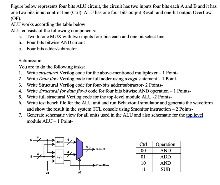
Figure below represents four bits ALU circuit, the circuit has two inputs four bits each A and B and it has one two bits input control line (Ctrl). ALU has one four bits output Result and one-bit output Overflow (OF). ALU works according the table below ALU consists of the following components: a. Two to one MUX with two inputs four bits each and one bit select line b. Four bits bitwise AND circuit c. Four bits adder/subtractor. Submission You are to do the following tasks: 1. Write structural Verilog code for the above-mentioned multiplexer - 1 Point- 2. Write Data flow Verilog code for full adder using assign statement - 1 Point- 3. Write Structural Verilog code for four-bits adder/subtractor- 2 Points- 4. Write Structural (or data flow) code for four bits bitwise AND operation - 1 Points- 5. Write full structural Verilog code for the top-level module ALU-2 Points- 6. Write test bench file for the ALU unit and run Behavioral simulator and generate the waveform and show the result in the system TCL console using $monitor instruction - 2 Points- 7. Generate schematic view for all units used in the ALU and also schematic for the top level module ALU - 1 Point- AND Result Ctrl 00 01 10 11 Operation AND ADD AND SUB Overflow c1 Figure below represents four bits ALU circuit, the circuit has two inputs four bits each A and B and it has one two bits input control line (Ctrl). ALU has one four bits output Result and one-bit output Overflow (OF). ALU works according the table below ALU consists of the following components: a. Two to one MUX with two inputs four bits each and one bit select line b. Four bits bitwise AND circuit c. Four bits adder/subtractor. Submission You are to do the following tasks: 1. Write structural Verilog code for the above-mentioned multiplexer - 1 Point- 2. Write Data flow Verilog code for full adder using assign statement - 1 Point- 3. Write Structural Verilog code for four-bits adder/subtractor- 2 Points- 4. Write Structural (or data flow) code for four bits bitwise AND operation - 1 Points- 5. Write full structural Verilog code for the top-level module ALU-2 Points- 6. Write test bench file for the ALU unit and run Behavioral simulator and generate the waveform and show the result in the system TCL console using $monitor instruction - 2 Points- 7. Generate schematic view for all units used in the ALU and also schematic for the top level module ALU - 1 Point- AND Result Ctrl 00 01 10 11 Operation AND ADD AND SUB Overflow c1
Step by Step Solution
There are 3 Steps involved in it

Get step-by-step solutions from verified subject matter experts