

Question: We are given the control system shown below where the excitation is the voltage source vS(t) and the response is the voltage vC (t). Assume
We are given the control system shown below where the excitation is the voltage source vS(t) and the response is the voltage vC (t). Assume that the opamps are ideal.
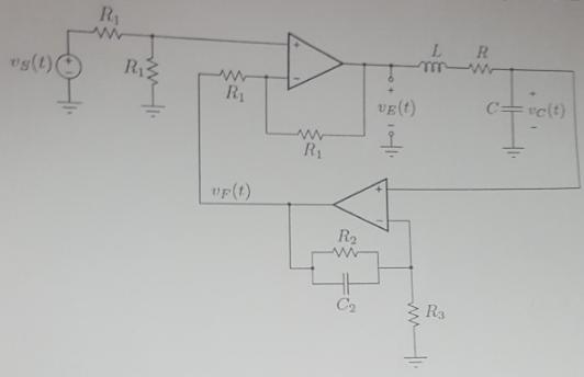
a. Given that R 1 = 10kΩ, determine find V E (s) as a function of voltages V s (S) and V F (S).
b. Given that R = 1Ω, I = 100mH and C = 100mF, determine that transfer function Vc(S)/V E (s).
c. Given that R2 = 10K Ω, R3 = 1kΩ and C2 = 100μF, determine the transfer function V F (s)/V C (s).
d. Construct a block diagram for the overall system showing voltages V s (S) and V F (S).
e. Determine the transfer function Vc(S)/V E (s).
Ry "s(t)( R1 vE(t) relt) R1 "F(t) R2 Ca Ra
Step by Step Solution
3.37 Rating (150 Votes )
There are 3 Steps involved in it
Lets break down the steps for each part of the problem a Determine VEs as a function of Vss and VFs ... View full answer

Get step-by-step solutions from verified subject matter experts