

Question: We want to design a 16-bit calculator that performs the following operations: addition, subtraction, increment, Shift left, Shift right, and 2 logical operations. The calculator
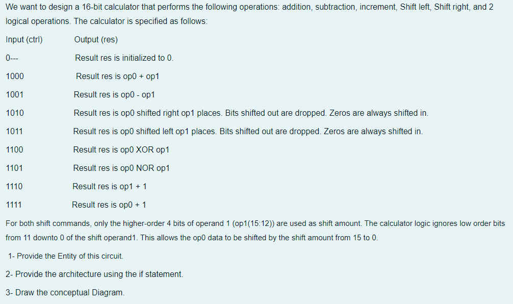
We want to design a 16-bit calculator that performs the following operations: addition, subtraction, increment, Shift left, Shift right, and 2 logical operations. The calculator is specified as follows: Input (ctrl) Output (res) 0--- Result res is initialized to 0. 1000 Result res is op + op1 1001 Result res is opo-op1 1010 Result res is opo shifted right op 1 places. Bits shifted out are dropped. Zeros are always shifted in. 1011 Result res is op shifted left op 1 places. Bits shifted out are dropped. Zeros are always shifted in. 1100 Result res is op0 XOR op 1 1101 Result res is opO NOR op1 1110 Result res is op 1 + 1 1111 Result res is op0 + 1 For both shift commands, only the higher-order 4 bits of operand 1 (op1(15.12)) are used as shift amount. The calculator logic ignores low order bits from 11 downto 0 of the shift operand1. This allows the opO data to be shifted by the shift amount from 15 to 0. 1- Provide the Entity of this circuit. 2- Provide the architecture using the if statement. 3- Draw the conceptual Diagram. We want to design a 16-bit calculator that performs the following operations: addition, subtraction, increment, Shift left, Shift right, and 2 logical operations. The calculator is specified as follows: Input (ctrl) Output (res) 0--- Result res is initialized to 0. 1000 Result res is op + op1 1001 Result res is opo-op1 1010 Result res is opo shifted right op 1 places. Bits shifted out are dropped. Zeros are always shifted in. 1011 Result res is op shifted left op 1 places. Bits shifted out are dropped. Zeros are always shifted in. 1100 Result res is op0 XOR op 1 1101 Result res is opO NOR op1 1110 Result res is op 1 + 1 1111 Result res is op0 + 1 For both shift commands, only the higher-order 4 bits of operand 1 (op1(15.12)) are used as shift amount. The calculator logic ignores low order bits from 11 downto 0 of the shift operand1. This allows the opO data to be shifted by the shift amount from 15 to 0. 1- Provide the Entity of this circuit. 2- Provide the architecture using the if statement. 3- Draw the conceptual Diagram
Step by Step Solution
There are 3 Steps involved in it

Get step-by-step solutions from verified subject matter experts