

Question: what extra information is needed? The static and dynamic balancing apparatus TM102 is used for practical 1 (Balancing the mass on the rotating shaft). This
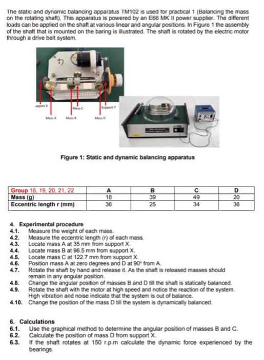
The static and dynamic balancing apparatus TM102 is used for practical 1 (Balancing the mass on the rotating shaft). This apparatus is powered by an E66 MK II power supplier. The different loads can be applied on the shaft at various linear and angular positions. In Figure 1 the assembly of the shaft that is mounted on the baring is illustrated. The shaft is rotated by the electric motor through a drive belt system. Mass Me Figure 1: Static and dynamic balancing apparatus Group 18, 19, 20, 21, 22 Mass (9) Eccentric length (mm) 18 36 B 39 25 49 34 D 20 36 4. Experimental procedure 4.1. Measure the weight of each mass. 4.2. Measure the eccentric length (n) of each mass 4.3. Locate mass A at 35 mm from support X 4.4. Locate mass B at 96.5 mm from support X 4.5. Locate mass C at 122.7 mm from support X 4.6. Position mass A at zero degrees and D at 90 from A 4.7. Rotate the shaft by hand and release it. As the shaft is released masses should remain in any angular position 4.8. Change the angular position of masses B and D till the shaft is statically balanced. 4.9. Rotate the shaft with the motor at high speed and notice the reaction of the system. High vibration and noise indicate that the system is out of balance. 4.10. Change the position of the mass D till the system is dynamically balanced. 6. Calculations 6.1. Use the graphical method to determine the angular position of masses B and C. Calculate the position of mass D from support X 6.3. If the shaft rotates at 150 rp.m calculate the dynamic force experienced by the bearings 6.2
Step by Step Solution
There are 3 Steps involved in it

Get step-by-step solutions from verified subject matter experts