

Question: What is the profile or side view in Solidworks program? Explain. Features Sketch Surface Sheet Metal Eva SOLIDWORKS Add-ins Simulation SOLIDWORKS MED Features Sketch Surfaces
 What is the profile or side view in Solidworks program? Explain.
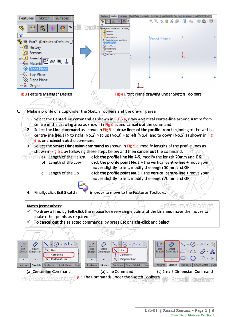
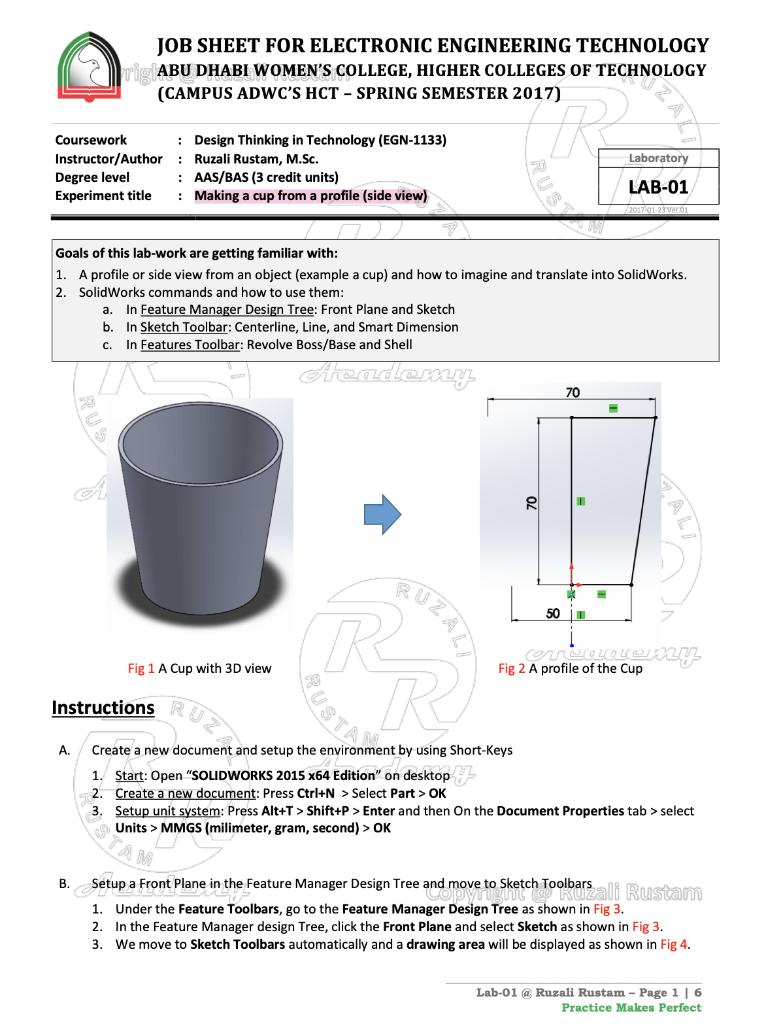
Features Sketch Surface Sheet Metal Eva SOLIDWORKS Add-ins Simulation SOLIDWORKS MED Features Sketch Surfaces e hli Rusta Samaris Detoks Front Plane History Sensor PA Material not specified Front Plane 9. Top Plane tight Plane 1. Origin Slutch Part7 (Default_ - History Sensors -A Annotat SE Material eori Front Plane Top Plane Right Plane + Origin Fig 3 Feature Manager Design Fig 4 Front Plane drawing under Sketch Toolbars RUSTRO C. Make a profile of a cup under the Sketch Toolbars and the drawing area 1. Select the Centerline command as shown in Fig 5.a, draw a vertical centre-line around 40mm from centre of the drawing area as shown in Fig 6.a, and cancel out the command. 2. Select the Line command as shown in Fig 5.b, draw lines of the profile from beginning of the vertical centre-line (No.1) > to right (No.2) > to up (No.3) > to left (No.4) and to down (No.5) as shown in Fig 6.b, and cancel out the command. 3. Select the Smart Dimension command as shown in Fig 5.c, modify lengths of the profile lines as shown in Fig 6.c by following these steps below and then cancel out the command. Aa) Length of the Height : click the profile line No.4-5, modify the length 70mm and OK. b) Length of the Low : click the profile point No.2 + the vertical centre-line + move your mouse slightly to left, modify the length 50mm and OK. c) Length of the Up : click the profile point No.3 + the vertical centre-line + move your mouse slightly to left, modify the length 70mm and OK. ROS MUSTA 4. Finally, click Exit Sketch in order to move to the Features Toolbars. Academy Notes (remember) To draw a line: by Left-click the mouse for every single points of the Line and move the mouse to make other points as required. To cancel out the selected commands: by press Esc or right-click and Select FoN- o-N- Exit Smart Exit Smart Line Exit Smart Sketch Dimension Sketch Dimension Line Sketch Dimension O Centerline Centerline Midpoint Line Midpoint Line Features Sketch Surfaces Sheet Metal Evals Features Sketch Surfaces Sheet Metal Evali Features Sketch Surfaces Sheet Metal Eval (a) Centerline Command (b) Line Command (c) Smart Dimension Command Fig 5 The Commands under the Sketch Toolbars Azademy.fi e Sketch Toolbars @ Ruzali Rustam Lab-01 @ Ruzali Rustam - Page 2 | 6 Practice Makes Perfect JOB SHEET FOR ELECTRONIC ENGINEERING TECHNOLOGY rig ABU DHABI WOMEN'S COLLEGE, HIGHER COLLEGES OF TECHNOLOGY (CAMPUS ADWC'S HCT - SPRING SEMESTER 2017) " Laboratory Coursework Instructor/Author Degree level Experiment title : Design Thinking in Technology (EGN-1133) : Ruzali Rustam, M.Sc. : AAS/BAS (3 credit units) : Making a cup from a profile (side view) LAB-01 sna 23 vero1 Goals of this lab-work are getting familiar with: 1. A profile or side view from an object (example a cup) and how to imagine and translate into SolidWorks. 2 SolidWorks commands and how to use them: In Feature Manager Design Tree: Front Plane and Sketch b. In Sketch Toolbar: Centerline, Line, and Smart Dimension In Features Toolbar: Revolve Boss/Base and Shell a. c. Academy 70 70 500 UZAL genoten Fig 2 A profile of the Cup Fig 1 A Cup with 3D view Instructions A. R Create a new document and setup the environment by using Short-Keys 1. Start: Open "SOLIDWORKS 2015 x64 Edition" on desktop 2. Create a new document: Press Ctrl+N > Select Part > OK 3. Setup unit system: Press Alt+T > Shift+P > Enter and then On the Document Properties tab > select Units > MMGS (milimeter, gram, second) > OK acon, 1993 B. Setup a Front Plane in the Feature Manager Design Tree and move to sketch Toolbars ali Rustam 1. Under the Feature Toolbars, go to the Feature Manager Design Tree as shown in Fig 3. 2. In the Feature Manager design Tree, click the Front Plane and select Sketch as shown in Fig 3. 3. We move to Sketch Toolbars automatically and a drawing area will be displayed as shown in Fig 4. Lab-01 @ Ruzali Rustam - Page 16 Practice Makes Perfect Review Questions: Please answer these questions related to this lab. ( R 1. What is the profile or side view? Explain briefly. Answer: BUZA RUSTA heade
Step by Step Solution
There are 3 Steps involved in it

Get step-by-step solutions from verified subject matter experts