

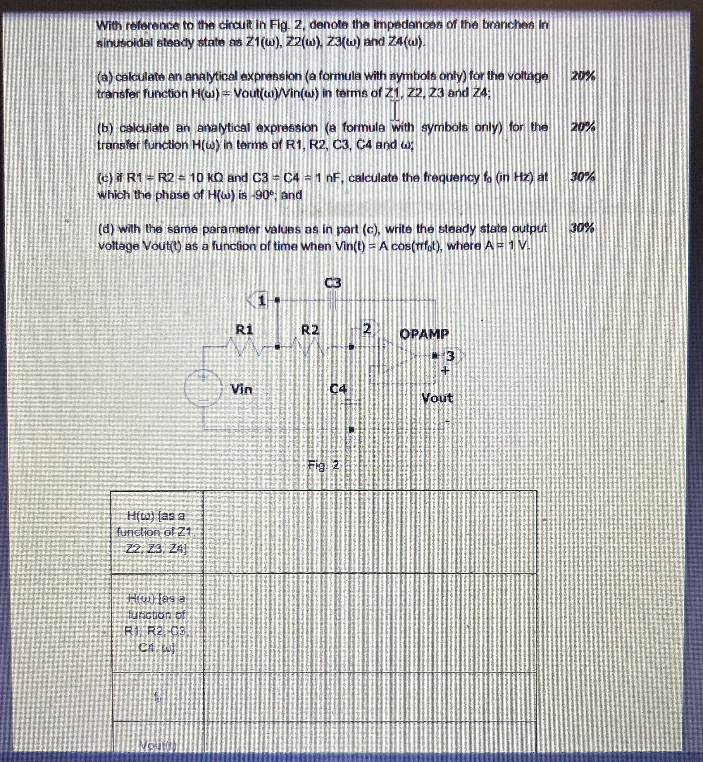
Question: With reference to the circuit in Fig. 2 , denote the impedances of the branches in sinusoidal steady state as Z 1 ( ) ,
With reference to the circuit in Fig. denote the impedances of the branches in sinusoidal steady state as and
a calculate an analytical expression a formula with symbols only for the voltage transfer function Vout in terms of and ;
b calculate an analytical expression a formula with symbols only for the transfer function in terms of R R C C and ;
c if and calculate the frequency in Hz at which the phase of is ; and
d with the same parameter values as in part c write the steady state output voltage Voutt as a function of time when VinAcos where
Fig.
Step by Step Solution
There are 3 Steps involved in it
1 Expert Approved Answer
Step: 1 Unlock

Question Has Been Solved by an Expert!
Get step-by-step solutions from verified subject matter experts
Step: 2 Unlock
Step: 3 Unlock