

Question: 1. On the part below, apply postion controls to allow the holes to move 0.4 side to side but only 0.1 in the up
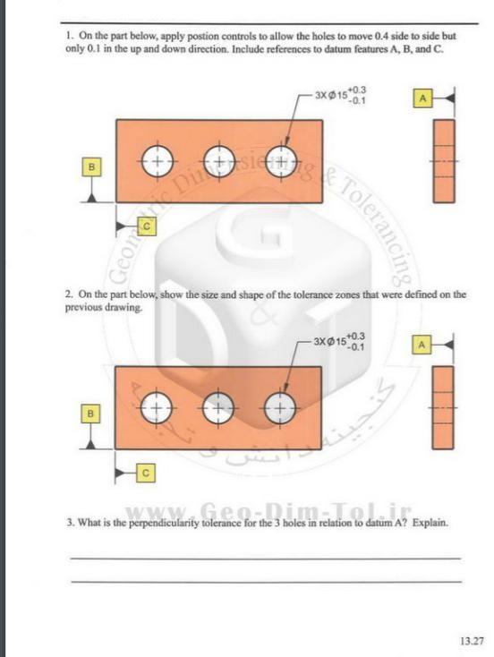
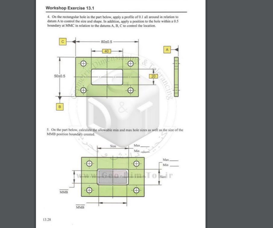
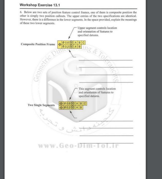
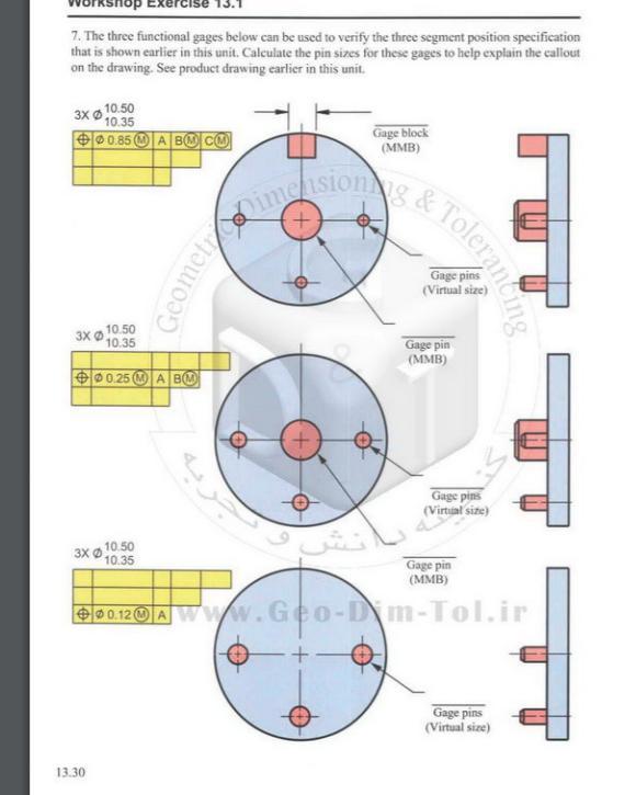
1. On the part below, apply postion controls to allow the holes to move 0.4 side to side but only 0.1 in the up and down direction, Include references to datum features A, B, and c. - 3x15*0.3 P-0.1 Dinsi Tolerand 2. On the part below, show the size and shape of the tolerance zones that were defined on the previous drawing. 3X15*0.3 -0.1 www.Geo.Dim Lolir. 3. What is the perpendicularity tolerance for the 3 holes in relation to datum A? Explain. 13.27 Workshop Exercise 13.1 4. On the rectangular hole in the part below, apply a profile of 0.1 all around in relation to datum A to control the size and shape. In addition, apply a position to the hole within a 0.5 boundary at MMC in relation to the datums A, B, C to control the location. 8010.5- 40 5020.5 5. On the part below, calculate the allowable min and max hole sizes as well as the size of the MMB position boundary created. Size Max, Min Max. Min Gen.imTo Siel r MMB MMB 13.28 Wrancine Workshop Exercise 13.1 6. Below are two sets of position feature control frames, one of them is composite position the other is simply two position callouts. The upper entries of the two specifications are identical. However, there is a difference in the lower segments. In the space provided, explain the meanings of these two lower segments. - Upper segment controls location and orientation of features to specified datums. Composite Position Frame 00.6ABC ing Geometric DinIA This segment controls location and orientation of features to specified datums. e 0.6 MA BC 0.2 MA B Two Single Segments www.Geo-Dim-Tol.ir 7. The three functional gages below can be used to verify the three segment position specification that is shown earlier in this unit. Calculate the pin sizes for these gages to help explain the callout on the drawing. See product drawing earlier in this unit. 10.50 3X 10.35 00.85 (OA BO CO Gage block (MMB) ometoimeisIong& ToleranC Gage pins (Virtual size) 10.50 3X O 10.35 Gage pin (MMB) $0 0.25 A BM Gage pins (Virtual size) 10.50 3X O 10.35 Gage pin (MMB) O0 0.12 M AWWW.Geo-Dim-Tol.ir 0.12 O A Gage pins (Virtual size) 13.30
Step by Step Solution
3.39 Rating (158 Votes )
There are 3 Steps involved in it
Lets go through the workshop exercises step by step 1 Position Controls for Holes Objective Apply position controls to allow the holes to move 04 unit... View full answer

Get step-by-step solutions from verified subject matter experts