

Question: Write down the truth table of a 2-input NOR gate and the Boolean expression for its output in the product of sums (POS) form.
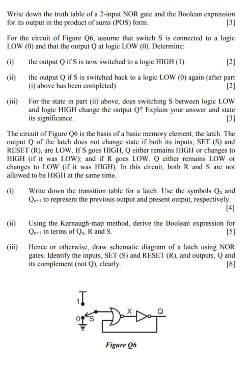
Write down the truth table of a 2-input NOR gate and the Boolean expression for its output in the product of sums (POS) form. [3] For the circuit of Figure Q6, assume that switch S is connected to a logic LOW (0) and that the output Q at logic LOW (0). Determine: (i) the output Q if S is now switched to a logic HIGH (1). (ii) [2] the output Q if S is switched back to a logic LOW (0) again (after part (i) above has been completed). [2] (iii) For the state in part (ii) above, does switching S between logic LOW and logic HIGH change the output Q? Explain your answer and state its significance. [3] The circuit of Figure Q6 is the basis of a basic memory element, the latch. The output Q of the latch does not change state if both its inputs, SET (S) and RESET (R), are LOW. If S goes HIGH, Q either remains HIGH or changes to HIGH (if it was LOW); and if R goes LOW, Q either remains LOW or changes to LOW (if it was HIGH). In this circuit, both R and S are not allowed to be HIGH at the same time. (i) Write down the transition table for a latch. Use the symbols Qn and Qn+1 to represent the previous output and present output, respectively. [4] (ii) Using the Karnaugh-map method, derive the Boolean expression for Qn+1 in terms of Q, R and S. [5] (iii) Hence or otherwise, draw schematic diagram of a latch using NOR gates. Identify the inputs, SET (S) and RESET (R), and outputs, Q and its complement (not Q), clearly. [6] Figure Q6
Step by Step Solution
There are 3 Steps involved in it

Get step-by-step solutions from verified subject matter experts