

Question: Write the arduino code for the system above Design a controlled RG LED system Requirments: The system should include Red LED, Green LED, LCD, Potentiometer
 Write the arduino code for the system above
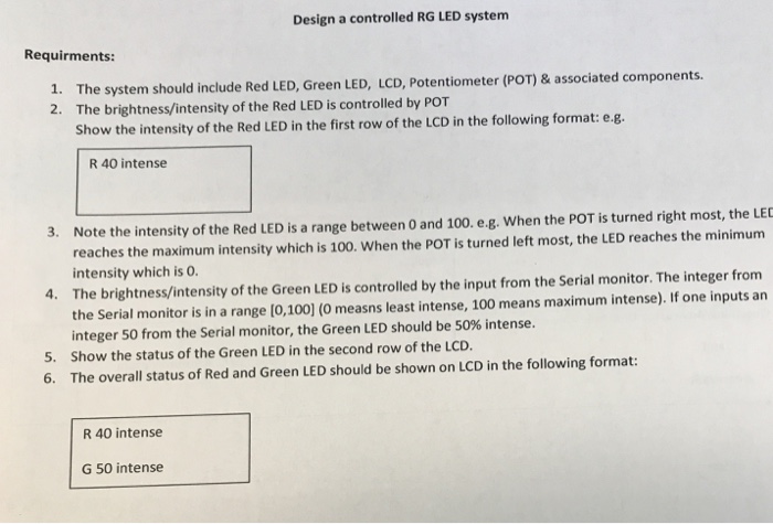
 Design a controlled RG LED system Requirments: The system should include Red LED, Green LED, LCD, Potentiometer (POT)& associated components. The brightness/intensity of the Red LED is controlled by POT Show the intensity of the Red LED in the first row of the LCD in the following format: e.g. 1. 2. R 40 intense 3. Note the intensity of the Red LED is a range between 0 and 100. e.g. When the POT is turned right most, the LEC 4. The brightness/intensity of the Green LED is controlled by the input from the Serial monitor. The integer from 5. Show the status of the Green LED in the second row of the LCD reaches the maximum intensity which is 100. When the POT is turned left most, the LED reaches the minimum intensity which is O. the Serial monitor is in a range (0,100] (0 measns least intense, 100 means maximum intense), If one inputs an integer 50 from the Serial monitor, the Green LED should be 50% intense. 6. The overall status of Red and Green LED should be shown on LCD in the following format R 40 intense G 50 intense
Step by Step Solution
There are 3 Steps involved in it

Get step-by-step solutions from verified subject matter experts